Take a 4.0 m wall at PGA 0.12 g. Seismic loading gives you 17 % more thrust than static and 31 % more moment at the base. The Mononobe-Okabe (M-O) method gives the seismic active thrust on a wall that can yield as \(P_{AE} = \frac{1}{2} K_{AE} \gamma H^2 (1-k_v)\). Take \(k_h = a_h/g\). Without a site-specific study, take \(k_v = \frac{2}{3} k_h\). Apply the seismic increment at 0.6H. The method holds only while \(\phi - \beta \ge \psi\) and nothing under or behind the wall can liquefy.
It’s a pseudo-static extension of the Coulomb wedge. Mononobe and Okabe published it in the 1920s, and Seed and Whitman simplified it in 1970. The Canadian Foundation Engineering Manual, 5th edition (CFEM 2023), sets it out in Section 18.7.1, and the equations below follow that section.
When NBC 2020 asks for seismic earth pressure
Three sentences in Part 4 decide whether you need this at all:
| Clause | What it says |
|---|---|
| NBCC 4.1.8.16.(7) | Where the Seismic Category is SC3 or SC4, basement walls must resist earthquake lateral pressures from backfill or natural ground. Note A-4.1.8.16.(7) points to the Commentary for the method. |
| NBCC 4.1.3.2.(10) | That pressure is part of E in load combination 5, 1.0D + 1.0E (Table 4.1.3.2.-A). Static earth pressure H carries a load factor of 1.5 under 4.1.3.2.(4). |
| NBCC 4.1.8.16.(10) | Liquefaction potential must be evaluated. That result decides whether M-O is usable. |
The factors and companion loads in combination 5 are where this force ends up. A freestanding site wall isn’t a basement wall, so Part 4 doesn’t name it. In BC the EGBC retaining wall guidelines fill that gap with a no-collapse target for walls from 1.2 m.
In practice: if the building is SC3 or SC4, its basement walls need a seismic earth pressure in combination 5. Basement walls braced by floors are rigid and take the at-rest increment (below); M-O covers cantilever and gravity walls that can yield.
The M-O equations (CFEM Section 18.7.1)
The total thrust is the static Coulomb thrust plus a seismic increment (CFEM Eqs 18.20 to 18.25):
$$P_{AE} = P_A + \Delta P_{AE}$$$$P_A = \frac{1}{2} K_A \cdot \gamma \cdot H^2 \qquad P_{AE} = \frac{1}{2} K_{AE} \cdot \gamma \cdot H^2 \cdot (1-k_v)$$$$K_{\mathrm{A}}=\frac{\cos ^2(\phi-\theta)}{\cos ^2 \theta \ \cos (\delta+\theta)\left[1+\sqrt{\frac{\sin (\delta+\phi) \ \sin (\phi-\beta)}{\cos (\delta+\theta) \ \cos (\beta-\theta)}}\right]^2}$$$$K_{\mathrm{AE}}=\frac{\cos ^2(\phi-\theta-\psi)}{\cos \psi \ \cos ^2 \theta \ \cos (\delta+\theta+\psi)\left[1+\sqrt{\frac{\sin (\delta+\phi) \ \sin (\phi-\beta-\psi)}{\cos (\delta+\theta+\psi) \ \cos (\beta-\theta)}}\right]^2}$$
- \(\phi\) - backfill friction angle
- \(\theta\) - slope of the back face of the wall from vertical
- \(\beta\) - backfill slope from horizontal
- \(\delta\) - wall-backfill interface friction angle
- \(\psi = \tan^{-1}[k_h/(1-k_v)]\) - angle of the seismic coefficient, valid for \(\phi - \beta \ge \psi\)
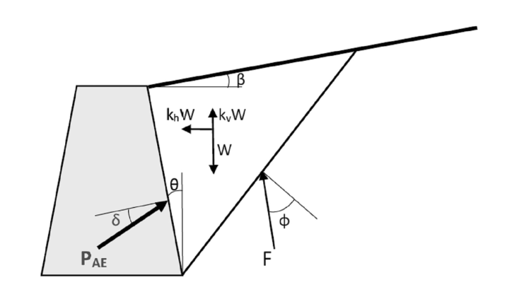 Forces on a flexible wall in the M-O method. Source: Canadian Foundation Engineering Manual, 5th edition, Fig. 18.34
Set \(k_h = 0\) and \(K_{AE}\) collapses to \(K_A\), which is a quick check on a spreadsheet.
Worked example: a 4.0 m cantilever wall
The inputs are the default case of a cantilever wall check that runs these steps, then sliding, bearing and the stem, toe and heel steel . That way you can check every number below against it. A 3.5 m stem sits on a 0.5 m base. That makes H = 4.0 m on a vertical virtual back through the heel. Backfill \(\gamma = 18\ \mathrm{kN/m^3}\), \(\phi = 34^\circ\), level backfill (\(\beta = 0\)), \(\delta = 0\) on the virtual back, PGA = 0.12 g.
Two judgment calls come before any arithmetic:
- Check that the method applies. A cantilever on a spread footing can slide and rotate, so active pressure mobilizes. The backfill must be drained, cohesionless and non-liquefiable under NBCC 4.1.8.16.(10).
- Get the seismic coefficients. Pull PGA from the NRCan NBC 2020 seismic hazard tool for the site designation of the soil below the base, not the backfill. NBCC 4.1.8.4 prefers \(X_V\) from a measured \(V_{s30}\); \(X_S\) from \(N_{60}\) or \(s_u\) is the fallback. CFEM’s alternative route, \(F(PGA) \cdot PGA\), cites the NBC 2015 site classes, so don’t mix it with 2020 hazard values. Here \(k_h = 0.12\) and \(k_v = \frac{2}{3} k_h = 0.08\).
The rest is arithmetic:
Seismic earth thrust on a 4.0 m cantilever wall (M-O)
Drained, cohesionless, non-liquefiable backfill; wall free to yield (active state)
9 input values\(H = 4.0\) m, \(\phi = 34\)°, \(k_h = 0.12\) ...
Step 1: Seismic inertia angle\(\psi = 7.43^\circ\)
Step 2: Static active coefficient (Coulomb)\(K_A = 0.283\)
Step 3: Seismic active coefficient (M-O)\(K_{AE} = 0.361\)
Step 4: Static thrust\(P_A = 40.7\ \text{kN/m}\)
Step 5: Total seismic thrust\(P_{AE} = 47.8\ \text{kN/m}\)
Step 6: Seismic increment\(\Delta P_{AE} = 7.0\ \text{kN/m}\)
Step 7: Resultant height\(h = 1.49\ \text{m}\)
Step 8: Moment at the base\(M_{AE} = 71.2\ \text{kN·m/m}\)
The wall check reports the same 40.7 and 7.0 kN/m. Change the PGA, friction angle or backslope there and you get your own wall, with sliding, bearing and the reinforcement checked in the same pass.
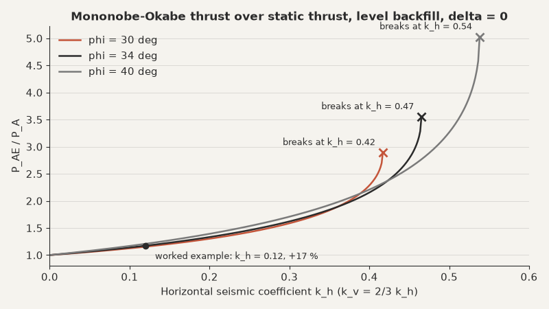
Up to \(k_h\) of about 0.2, the seismic increment stays within about a third of the static thrust. Past 0.35 it climbs steeply toward the point where the equation breaks, so a high-hazard site needs a closer look at \(\phi\) and \(\beta\) before you trust the number.
Wall inertia: the force M-O leaves out
CFEM 18.7.5.3 says it plainly: these methods treat the backfill as a rigid block and ignore the inertia of the wall. On a cantilever wall, the concrete and the soil block over the heel move with the wall. In the example they weigh 219.9 kN/m, so \(k_h W\) = 0.12 x 219.9 = 26.4 kN/m. That’s nearly four times the 7.0 kN/m M-O increment.
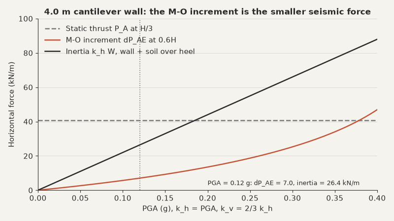
Before checking sliding and overturning, include \(k_h W\) for the wall and the heel soil, each at its own centroid. Adding it at full value on top of the full M-O thrust is conservative, since the two peaks don’t necessarily coincide. CFEM 18.7.6.1 relaxes this for MSE walls by pairing 100 % of one with 50 % of the other. Either way, the M-O increment alone undersells the seismic case on any wall with a long heel.
Where M-O stops working
- Rigid walls. A basement wall braced by floor diaphragms can’t move enough to mobilize active pressure. Use at-rest: \(K_0 = 1 - \sin\phi\), with \(\Delta P_{0E} = k_h \gamma H^2\) at 0.58H (CFEM Eqs 18.36 and 18.39). For the example geometry that’s 34.6 kN/m, five times the M-O increment.
- Saturated backfill. Replace \(\gamma\) with \(\gamma'\) and raise \(\psi\): \(\tan\psi' = \frac{G_s}{G_s-1}\tan\psi\) for permeable backfill, plus static and dynamic water pressure. For backfill less permeable than 0.01 m/s, use \(\tan\psi'' = \frac{G_s+e}{G_s-1}\tan\psi\) with static water only (CFEM Eqs 18.34 and 18.35).
- \(\phi - \beta < \psi\). The square root goes negative and \(K_{AE}\) is indeterminate. Model the wall in a slope stability program with the seismic coefficient, and solve for the external force that brings the factor of safety to 1.0 (CFEM 18.7.4).
- Liquefiable soils. CFEM notes that retaining walls have performed well in past earthquakes except where liquefaction occurred. M-O isn’t appropriate for soils that lose significant strength.
- Passive side. The M-O passive coefficient \(K_{PE}\) overpredicts passive thrust, particularly for \(\delta > \phi/2\) (CFEM 18.7.1.3). Keep \(\delta\) low on the toe side.
CFEM 18.7.1.3 also cites Taiebat et al. (2014): basement walls founded on dense soil can be designed with M-O using \(k_h\) at 50 % to 60 % of \(a_h\).
When the wall is braced, the backfill can liquefy or the equation breaks, switch to at-rest, limit equilibrium or a displacement method such as Newmark sliding block. The analysis and verification part of the PBD toolkit covers those.
Before the wall goes to review
- Confirm the site designation under the footing, pull the NBC 2020 PGA, and check \(\phi - \beta \ge \psi\) before computing anything.
- Carry \(\Delta P_{AE}\) at 0.6H, plus \(k_h W\) for the wall and heel soil, into load combination 5.
- If the wall is braced or the soil can liquefy, M-O is the wrong tool: use at-rest pressures or a displacement analysis.