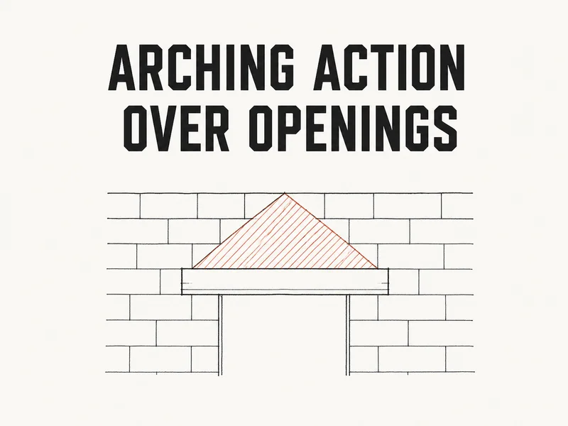
A lintel over a 2.8 m door with a roof beam bearing 900 mm above it needs about 98 kNm of factored moment. Without arching and without spreading the beam load, the same lintel needs 123 kNm. It’s tempting to credit that 20 percent drop to arching, but arching accounts for only about 2 kNm of it.
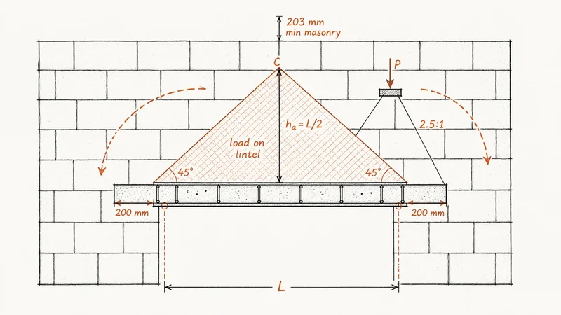
The rule: under arching, the lintel carries only the wall inside a 45 degree triangle on its span, with the apex at \(L/2\). That holds when at least 203 mm of masonry sits above the apex and no distributed floor or roof load bears below that band. Concentrated loads still go to the lintel in full, spread through the masonry per CSA S304-14 Cl. 7.14.2: 2.5:1 through hollow block, 45 degrees through fully grouted masonry. The steps below follow the edition NBC 2020 references, S304-14.
Draw the 45 degree triangle and find the apex
Take the span \(L\) as the clear opening plus one bearing length, centre to centre of the bearings. Rise at 45 degrees from each end and the two lines meet at the apex, \(h_a = L/2\) above the lintel. The wall inside that triangle is the load on the lintel. The wall outside it arches over to the piers on either side.
The triangle gives a triangular load, zero at the supports and \(w_{wall} h_a\) at midspan, where \(w_{wall}\) is the wall weight per unit area of wall face. Its midspan moment is:
$$M_t = \frac{w_t L^2}{12}, \quad w_t = w_{wall} h_a$$Add the lintel self-weight as a uniform load, \(w_s L^2/8\). On a 3.0 m span the apex sits 1.5 m up. Mark it on the elevation before anything else, since the depth and floor checks both measure from it.
Check three conditions before you take the reduction
CSA S304-14 has no arching rule for lintels; its Annex F arch provisions cover only empirical arches in veneer and nonloadbearing walls. The working rule comes from CMHA TEK 17-01D, so you have to justify it on your own drawings. Arching only forms when all three of these hold:
- Wall on each side to take the thrust. An arch pushes outward at its springing. Give the lintel at least 200 mm of bearing, and make sure the pier beside the opening is long enough to resist the horizontal kick. A narrow pier between two openings is the usual place this fails.
- At least 203 mm of masonry above the apex. The arch’s compression runs through that band. On a 3.0 m span you need masonry up to \(1500 + 203 = 1703\) mm above the lintel.
- No distributed floor or roof load below the arch. A slab or joist line bearing below \(h_a + 203\) mm interrupts the arch. Design the lintel for the full wall height plus that load as uniform loads. A concentrated load such as a beam does not stop the arch, TEK 17-01D only asks that loads inside the triangle be carried, so it goes to the lintel in full.
On a 3.0 m span, a floor bearing less than 1.7 m above the lintel rules arching out.
Spread the point load per S304-14 Cl. 7.14.2, not at 60 degrees
Arching does nothing for a concentrated load. A roof beam or joist girder bearing on the wall above the lintel is carried in full, whatever its height, and the calc sheet below carries all of it.
What you can do is spread it. CSA S304-14 Cl. 7.14.2 disperses a concentrated load from the edges of the bearing plate at 22 degrees to the vertical (2.5 vertical to 1 horizontal) through hollow or partly grouted masonry. Through solid brick or fully grouted masonry the angle opens to 45 degrees. For hollow block, the load at the lintel acts over:
$$l_p = b_p + \frac{2 h_p}{2.5} \le L$$where \(b_p\) is the bearing plate length and \(h_p\) is the height of the load above the lintel. Many textbooks spread at 60 degrees instead, \(b_p + 2 h_p / \tan 60^\circ\). For hollow block that’s a wider spread and a lower moment than S304 allows. For grouted masonry it’s narrower than the code’s 45 degrees and conservative: a fully grouted wall at 3.91 kPa in the example below would spread the load over 2300 mm and drop \(M_f\) to 80.3 kNm.
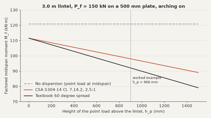
The higher the beam pocket, the more the spread pays. Pick the angle by the masonry between the plate and the lintel, and use the S304 rule so the clause on your calc sheet matches the number.
Worked example: a 2.8 m door lintel under a roof beam
A 190 mm block wall has a 2.8 m door opening and a 1000 mm deep fully grouted lintel with 200 mm bearings on grouted jamb cores. There’s 1.8 m of hollow block above the lintel at 2.11 kPa. A roof beam bears on a 500 mm plate centred over midspan, 900 mm above the lintel, with 81 kN dead and 32.4 kN snow (the Cb, Cw and Cs factors behind that snow load). Under NBCC 2020 Table 4.1.3.2.-A, \(1.25D + 1.5S\) governs, giving \(P_f = 150\) kN. The combinations are covered in the load combination post, where snow as the principal load sets the roof case.
The wall reaches 1800 mm, past the 1703 mm arching line. The roof beam is a concentrated load and no other roof framing bears on this wall, so arching applies to the wall and the beam load is added in full.
Factored moment on a 2.8 m masonry door lintel with arching and a dispersed roof beam load
45° arching triangle on the wall; point load carried in full and spread at 2.5:1 through the hollow block; simply supported lintel
16 input values\(L_o = 2800\) mm, \(h_{wall} = 1800\) mm, \(P_D = 81\) kN ...
Step 1: Span\(L = 3.00\ \text{m}\)
Step 2: Apex of the arching triangle\(h_a = 1.50\ \text{m}\)
Step 3: Peak triangular wall load\(w_t = 3.17\ \text{kN/m}\)
Step 4: Lintel self-weight\(w_s = 3.91\ \text{kN/m}\)
Step 5: Point load spread at the lintel\(l_p = 1220\ \text{mm}\)
Step 6: Moment per kN of spread load\(m_p = 0.5975\ \text{m}\)
Step 7: Dead load moment\(M_D = 55.17\ \text{kN·m}\)
Step 8: Snow load moment\(M_S = 19.36\ \text{kN·m}\)
Step 9: Factored moment\(M_f = 98.0\ \text{kN·m}\)
The lintel needs 98.0 kNm against a resistance of 142.5 kNm. Flexure and shear have margin to spare, but the 200 mm bearing is at its limit, so lengthen it before you trim the steel. The calc doesn’t check the wall under the beam plate or the piers for the arch thrust; check those separately under S304-14 Cl. 7.14, and keep the dispersion angle consistent with the grouting you assume there.
Where the saving actually comes from
Running the same lintel four ways shows where the saving comes from.
| Case | Wall load | Point load | \(M_f\) (kNm) |
|---|---|---|---|
| No arching, no spread | Full 1.8 m of wall | At midspan, zero width | 123 |
| Arching, no spread | 45 degree triangle | At midspan, zero width | 121 |
| Arching, S304 spread, hollow block | 45 degree triangle | 2.5:1 over 1220 mm | 98.0 |
| Arching, textbook spread | 45 degree triangle | 60 degrees over 1540 mm | 92.0 |
Arching saves 2.4 kNm here because 1.8 m of hollow block isn’t much weight. The point-load spread saves 23 kNm against a zero-width load at midspan: about 9 kNm from the 500 mm plate alone and about 14 kNm from spreading through 900 mm of masonry. Arching only starts to pay on tall walls: with 6.0 m of the same block above the lintel (beam still bearing at 900 mm, no floors in between), the triangle saves 14.8 kNm factored.
On a single-storey lintel under a beam, put your effort into the dispersion, and take arching only when the wall above is tall.
Where the method breaks
- Deep lintels. With \(L/h\) under 2 on a simple span, S304-14 Cl. 11.2.7.1 requires deep beam design with a reduced lever arm: \(d\) may be taken as 0.67 of the section depth, but not more than 0.35 times the span. A 1000 mm deep lintel on a 1.8 m span (\(L/h\) = 1.8) is in that range. Shear deformation also starts to matter at those proportions, as the deep member post shows with its span-to-depth comparison.
- Control joints at the jamb. A vertical joint at the edge of the opening can break the thrust path on that side, and S304-14 Cl. 7.14.2 stops any point-load spread at it. Arching is often still assumed with a joint there, but check where the thrust goes before you rely on it, or design for the full load.
- Short piers. A narrow pier between two openings may not resist the thrust of two arches. Check it, or treat both lintels as non-arching.
- Edition drift. S304:24 drops the \(\chi\) factor from the stress block (Cl. 12.2.1.6) and moves the beam clauses from Section 11 to Section 12, with shear in Cl. 12.3. NBC 2020 still references S304-14, so check which edition your jurisdiction adopts before you copy clause numbers between calcs.
Monday checklist
- On your next lintel, find \(h_a + 203\) mm and mark every floor and distributed roof bearing against it before you choose arching.
- Spread every point load per S304-14 Cl. 7.14.2, 2.5:1 through hollow block and 45 degrees through fully grouted masonry, and write the clause on the calc instead of 60 degrees.
- Check end bearing at 200 mm before the steel. On the example lintel it governs at 100 percent while flexure sits at 69 percent.