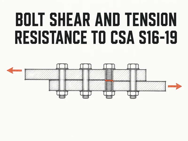
A 3/4 in A325 bolt in single shear resists 79.0 kN to CSA S16-19 Cl. 13.12.1.2 when the threads sit in the shear plane, and 112.9 kN when they don’t. In tension the same bolt gives 141.1 kN (Cl. 13.12.1.3). Those three numbers settle most simple shear tabs, lap splices and hanger connections before you open any software.
Getting there takes four checks: bolt shear, plate bearing and tear-out, tension with prying, and the combined shear-tension circle that per-bolt tables leave out.
Bolt resistance per bolt, at a glance
All values below are factored resistances for one bolt with one shear plane (\(m = 1\)), using \(\phi_b = 0.80\) from Cl. 13.12.1.1 and the bolt \(F_u\) values listed in the note to Cl. 13.12.1.2 (825 MPa for A325, 1035 MPa for A490, 830 MPa for A325M).
| Bolt | \(A_b\) (\(\text{mm}^2\)) | \(V_r\), threads out (kN) | \(V_r\), threads in (kN) | \(T_r\) (kN) |
|---|---|---|---|---|
| 3/4 in A325 | 285.0 | 112.9 | 79.0 | 141.1 |
| 7/8 in A325 | 387.9 | 153.6 | 107.5 | 192.0 |
| 1 in A325 | 506.7 | 200.7 | 140.5 | 250.8 |
| 3/4 in A490 | 285.0 | 141.6 | 99.1 | 177.0 |
| 7/8 in A490 | 387.9 | 192.7 | 134.9 | 240.9 |
| M20 A325M | 314.2 | 125.2 | 87.6 | 156.5 |
| M22 A325M | 380.1 | 151.4 | 106.0 | 189.3 |
Double the shear columns for double shear. These are bolt values only, and the plate still has to deliver them (Step 2).
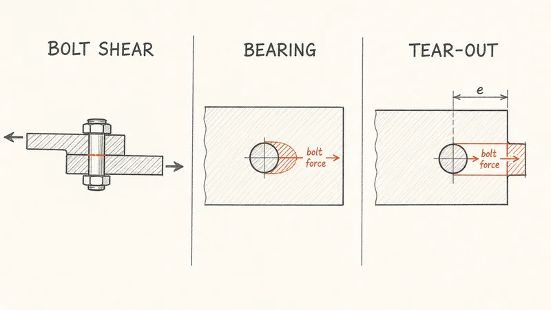
Step 1: bolt shear
Cl. 13.12.1.2(c) gives the shear resistance of the bolts in the joint:
$$V_r = 0.60\,\phi_b\,n\,m\,A_b\,F_u$$where \(n\) is the number of bolts, \(m\) the number of shear planes, \(A_b\) the nominal (shank) area and \(F_u\) the bolt tensile strength. The 0.60 is the ratio of shear to tensile strength of the bolt steel.
Two modifiers matter:
- Threads in the shear plane: multiply by 0.70. The threaded root has less area than the shank.
- Long lap splices: for joints longer than 760 mm between end fasteners, use 0.50 in place of 0.60, because the end bolts pick up more than their share before the joint can redistribute.
Threads-out is a detailing promise. It holds only if bolt length, grip and washer stack keep the thread runout clear of every shear plane, and the shop and erector know that. Thin plies mean a short grip, and a short grip puts the thread runout at or near the shear plane.
Use the threads-in value unless the drawings call out threads excluded and the grip actually works.
Step 2: bearing and tear-out at the plate
The bolt is only half the joint. Cl. 13.12.1.2(a) gives bearing on the plate at the hole:
$$B_r = 3\,\phi_{br}\,n\,t\,d\,F_u$$with \(\phi_{br} = 0.80\), plate thickness \(t\), bolt diameter \(d\) and the plate’s \(F_u\). Long slotted holes loaded across the slot use 2.4 in place of 3.
For a 3/4 in bolt in 10 mm 350W plate (\(F_u = 450\) MPa), bearing is 205.7 kN per bolt, 2.6 times the threads-in shear. Bearing almost never governs in plates 10 mm and thicker.
What does govern near an edge is tear-out. The same clause sends edge-close holes to Cl. 13.11, where the shear term of the block shear equation, applied along two planes tangent to the hole and running to the edge, gives:
$$R_{to} = \phi_u\,(0.6)\,A_{gv}\,\frac{F_y + F_u}{2}, \qquad A_{gv} = 2\,t\,e$$where \(R_{to}\) is the tear-out resistance per bolt, \(\phi_u = 0.75\) (Cl. 13.1) and \(e\) the end distance from the hole centre. Tear-out falls in proportion as the bolt moves toward the edge, while bolt shear and bearing don’t change.
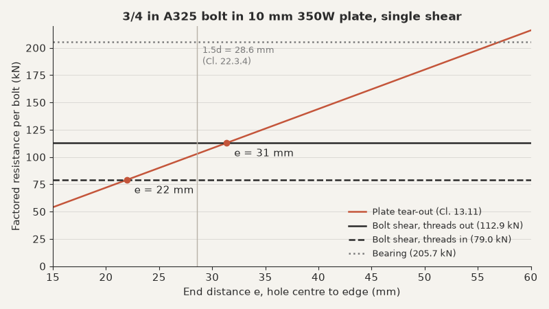
For 3/4 in A325 in 10 mm 350W plate, tear-out drops below bolt shear at \(e \approx 22\) mm with threads in and 31 mm with threads out. The Cl. 22.3.4 minimum of 1.5d (28.6 mm) for one or two bolts in line falls between those two. So with threads out, a bolt at the code minimum end distance is governed by plate tear-out.
Check tear-out at every end bolt with less than about 32 mm of end distance, even when bearing passes.
Worked example: a four-bolt lap splice
A 120 mm by 10 mm 350W plate carries a factored tension \(T_f = 280\) kN through a single-shear lap splice: four 3/4 in A325 bolts in one line at 75 mm pitch, 32 mm end distance (the Table 5 value that Cl. 22.3.4 sets for more than two bolts in line), threads not excluded. To swap in your own bolt size, grade, plate and edge distance, run the shear, bearing and tear-out checks per bolt ; it prints each step for the calc package.
- Bolt shear per bolt: \(0.60 \times 0.80 \times 285.0 \times 825 = 112.9\) kN, times 0.70 for threads = 79.0 kN. Joint length is \(3 \times 75 = 225\) mm, under 760 mm, so 0.60 stands.
- Bearing per bolt: \(3 \times 0.80 \times 10 \times 19.05 \times 450 = 205.7\) kN.
- Tear-out, end bolt: \(0.75 \times 0.6 \times (2 \times 10 \times 32) \times 400 = 115.2\) kN.
- Least per bolt: 79.0 kN (bolt shear). Bolt group \(4 \times 79.0 = 316\) kN.
- Plate net section and yield (Cl. 13.2): hole width 20.6 mm plus 2 mm (Cl. 12.3.2), so \(0.75 \times (120 - 22.6) \times 10 \times 450 = 329\) kN on the net section and \(0.90 \times 1200 \times 350 = 378\) kN on the gross section.
- Plate block shear (Cl. 13.11): bolt line out to one plate edge, \(U_t = 0.6\) taken conservatively for the one-sided block: \(0.75 \times (0.6 \times 487 \times 450 + 0.6 \times 2570 \times 400) = 561\) kN.
- Utilization: the bolt group governs at 316 kN, so \(280 / 316 = 0.89\). OK.
Specifying threads excluded would lift the bolt group to 451 kN, but the plate’s net section (329 kN) would then govern, so the joint gains only 4 percent. State the plate width, too: at 100 mm wide the net section drops to 261 kN and the plate fails before the bolts do.
Step 3: tension, prying included
Cl. 13.12.1.3 gives the tensile resistance of a bolt:
$$T_r = 0.75\,\phi_b\,A_b\,F_u$$The 0.75 already accounts for the threaded area, so there is no extra thread factor in tension.
The catch is the load side. The factored tension \(T_f\) is the external load plus any prying, and pretension does not reduce it. On a tee stub or a clip angle with a thin flange, the flange levers against its toe and the bolt carries that reaction on top of the applied load. The same flange bending is part of what makes a “pinned” end plate stiffer than a pin, as the moment-rotation discussion in the joint fixity post shows.
When a flange carries bolts in tension, find the prying force on your tee or angle flange before you compare \(T_f\) to \(T_r\).
Step 4: combined shear and tension
A bolt carrying both, as in a hanger bracket or a brace gusset to a column flange, has to satisfy the circular interaction of Cl. 13.12.1.4:
$$\left(\frac{V_f}{V_r}\right)^2 + \left(\frac{T_f}{T_r}\right)^2 \le 1$$Take a 3/4 in A325 bolt, threads in, with \(V_f = 50\) kN and \(T_f = 80\) kN (prying included):
$$\left(\frac{50}{79.0}\right)^2 + \left(\frac{80}{141.1}\right)^2 = 0.40 + 0.32 = 0.72 \le 1$$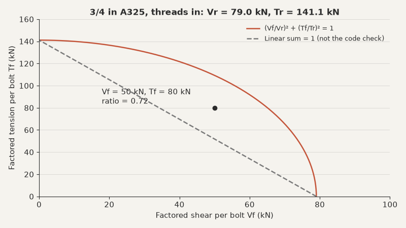
The circle is forgiving. A bolt at 50 percent of its shear resistance still keeps 87 percent of its tension resistance. A linear sum would have read 0.63 + 0.57 = 1.20 and failed the same bolt.
Per-bolt tables stop at \(V_r\) and \(T_r\), so take those values from Steps 1 and 3 and run the circle yourself.
Where this procedure stops
Everything above is a bearing-type joint at factored loads. Other cases need more:
- Slip-critical joints (Cl. 13.12.2): no slip at service loads, with the slip resistance from Cl. 13.12.2.2 and the slip coefficients from Table 3. The factored checks above still apply on top.
- Fatigue (Cl. 26.5): bolts in tension under cyclic load have their own limits.
- Oversize and slotted holes: edge and end distances are measured with the bolt at the worst end of the hole (Cl. 22.3.5.3). Oversize holes aren’t allowed in bearing-type joints at all (Cl. 22.3.5.2).
The load side matters as much as the resistance. Make sure \(V_f\) and \(T_f\) come from the governing NBCC case, which the load combination walkthrough covers.
Three things to do on your next bolted connection:
- Mark threads in or out on the drawings, and design to threads in unless the grip proves otherwise.
- Check tear-out at every end bolt with less than 32 mm of end distance.
- Add prying to \(T_f\), then run the circular interaction for any bolt carrying both shear and tension.
Based on: CSA S16-19 Design of steel structures, Cl. 13.11, 13.12 and 22.3