You’ve got a floor slab in your building model. Do you use membrane elements? Plate elements? Shell elements? The answer isn’t “whatever the software defaults to” — it depends entirely on what you’re trying to analyse. Pick the wrong element type and you’ll either miss critical behaviour or drown in unnecessary output.
This post covers the fundamentals of element selection — we’ll walk through membrane, plate, and shell elements, discuss their degrees of freedom, and look at practical scenarios where each makes sense.
What Are You Trying to Find?
Before you even open your analysis software, ask yourself: what response am I after?
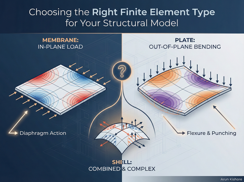
If you’re analysing a building for lateral loads (wind, seismic), your floor slabs act as diaphragms. They transfer horizontal forces in-plane — essentially tension, compression, and shear within the plane of the slab. That’s membrane behaviour.
If you’re analysing the same building for gravity loads, those same slabs now experience out-of-plane bending. You want moments and shears to design for flexure and punching. That’s plate behaviour.
Same slab. Different load case. Different element type.
Key Takeaway: The physical structure doesn’t change, but your model of it should match what you’re trying to capture. Don’t let the software make this decision for you.
Understanding Degrees of Freedom
Every finite element has a certain number of degrees of freedom (DOF) at each node. This determines what the element can “see” in terms of behaviour:
| Element Type | DOF per Node | What It Captures |
|---|---|---|
| Membrane | 2-3 | In-plane displacements (u, v), possibly in-plane rotation |
| Plate | 3 | Out-of-plane displacement (w), two rotations |
| Shell | 5-6 | All of the above combined |
More DOF means more equations to solve, more results to process, and more opportunities to misinterpret output. There’s no prize for using the most complex element available.
Membrane Elements - In-Plane Action Only
Membrane elements ignore bending stiffness entirely. They handle:
- Tension and compression
- In-plane shear
That’s it. If you apply an out-of-plane load to a membrane model, you’ll get garbage results (or the solver will simply fail).
When to Use Membrane Elements
Floor diaphragms under lateral load. When you’re running a lateral analysis and need to capture how the floor distributes horizontal forces to your lateral system, membrane elements work well. The slab isn’t bending under these loads — it’s acting like a deep, horizontal beam transferring shear.
Shear walls. For walls that primarily resist in-plane lateral forces, membrane elements can capture the essential behaviour. You’ll get in-plane stresses that you can integrate to find resultant forces for design.
Thin-walled structures. Ferro-cement tanks, thin metal panels, or other structures where bending stiffness is negligible compared to membrane stiffness.
Pro-Tip: If you’re modelling a floor slab purely for diaphragm action in a lateral analysis, a membrane model keeps things simple. You might even get away with a truss-type idealisation if you only need the load path, not the actual stress distribution.
What You Get Out
With membrane elements, you’ll see:
- \(\sigma_{xx}\), \(\sigma_{yy}\) (normal stresses in the x and y directions)
- \(\tau_{xx}\) (in-plane shear stress)
These are stresses, not member forces. If you need forces for design (like you would from a frame analysis), you’ll need to integrate these stresses across the element.
Plate Elements - Out-of-Plane Bending Only
Plate elements are the flip side of membranes. They handle:
- Out-of-plane bending (moments Mx, My, Mxy)
- Transverse shear (Vx, Vy)
They assume in-plane loads don’t exist. Apply axial forces to a plate model and you’ll get nothing useful.
When to Use Plate Elements
Floor slabs under gravity load. This is the classic application. You want to know bending moments for reinforcement design and shear forces for punching checks. Plate elements give you exactly that.
Flat plates, two-way slabs, pile caps. Any horizontal element where gravity loads create bending.
Degrees of Freedom
Each node has:
- One out-of-plane displacement (w)
- Two rotations (about the in-plane axes)
That’s 3 DOF per node, giving you the information you need for flexural design without the overhead of tracking in-plane behaviour you don’t care about.
For EITs: When you’re first learning FEM, start with plate models for gravity analysis of slabs. The output is more intuitive — you’ll see moment contours that look like what you’d expect from hand calculations or moment distribution methods.
Shell Elements - The General-Purpose Option
Shell elements combine membrane and plate behaviour. They can handle:
- In-plane tension, compression, and shear
- Out-of-plane bending and shear
- Curved geometry
With 5-6 DOF per node, shells are the most versatile — and the most demanding in terms of output interpretation.
When to Use Shell Elements
Curved structures. Cylindrical tanks, domes, barrel vaults. If your surface isn’t flat, you generally need shells because the geometry couples membrane and bending behaviour.
Combined loading scenarios. If your slab experiences significant lateral and gravity loads simultaneously and you want to capture both in a single model, shells handle that.
When you genuinely don’t know. Sometimes during preliminary design, you’re not sure which behaviour dominates. A shell model will capture both, and you can sort out the results later.
The Downside
Shell elements generate a lot of output. You’ll get membrane stresses, bending moments, and shear forces at every node. For a moderately fine mesh, that’s thousands of data points to check.
More critically, combined actions are harder to design for. Canadian concrete design (CSA A23.3) and steel design (CSA S16) are set up for separated actions — you design for moment, then check shear, then check axial. When you have combined membrane and bending stresses from a shell model, extracting the relevant design forces requires more effort.
Common Mistake: Defaulting to shell elements “just to be safe.” You’re not safer — you’re just drowning in data. If your slab is flat and loaded vertically, use plate elements. If it’s a diaphragm under lateral load, use membrane elements. Save shells for when you actually need them.
Frame Elements vs. Continuum Elements
There’s another distinction worth understanding: the difference between frame (beam/column) elements and continuum (membrane/plate/shell/solid) elements.
Frame elements use prismatic stiffness methods. One element spans joint to joint, and you get member forces directly — axial force, shear, moment. That’s what programs like S-Frame, ETABS, or SAP2000 do by default for beams and columns.
Continuum elements solve for stress fields, not member forces. You get σ and τ at integration points, and if you want forces, you integrate those stresses yourself (or use a tool feature like S-Frame’s wall integration lines).
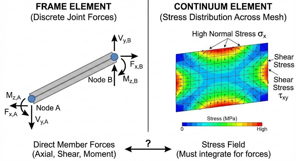
Comparison showing frame element with discrete joint forces vs. continuum element with stress distribution across mesh
This matters for walls. If you model a shear wall with a single vertical frame element, you’ll get axial force, shear, and moment at each end — directly usable for design. If you model it with shell elements, you’ll get stress contours that look impressive but require integration to get design forces.
Key Takeaway: Continuum models aren’t automatically “better” than frame models. They’re different tools. Use frame elements when discrete member forces are what you need. Use continuum elements when you need to understand stress distributions within a member.
Practical Decision Framework
Here’s how to think through element selection for common scenarios:
Scenario 1: Multi-storey building, lateral analysis
- Columns and beams: Frame elements (no question)
- Shear walls: Frame elements if you want member forces directly; shell or membrane if you need stress distributions or have complex geometry
- Floor slabs: Membrane elements for diaphragm action, or rigid diaphragm constraint if you don’t need internal diaphragm forces
Scenario 2: Multi-storey building, gravity analysis
- Columns and beams: Frame elements
- Floor slabs: Plate elements to get bending moments and shear
- Shear walls: Often not modelled for gravity (unless significant gravity load comes through them)
Scenario 3: Mat foundation
- The mat itself: Plate elements with soil springs or subgrade modulus
- Columns above: Frame elements
Scenario 4: Retaining wall
- If you need stress distribution: Plate or shell elements
- If you need overall stability and simple force diagrams: Possibly frame idealisation
Meshing Considerations
Once you’ve picked your element type, you need to decide on mesh density. This is a topic for another post, but the short version:
- Finer mesh = more accurate results (up to a point)
- Finer mesh = longer solve times and more output
- Boundary conditions (supports, connections) need nodes to attach to — if your mesh is too coarse, you might not have nodes where you need them
S-Frame, for example, lets you specify the number of elements along the longest edge of a panel. Start with a moderate mesh, check your results, and refine if the results aren’t converged. There’s always a trade-off between accuracy and practicality.
What to Do Next
On your next project with slabs: Deliberately choose between membrane and plate elements based on the load case. Don’t accept the default.
Review your existing models: Are you using shell elements where plate or membrane would suffice? Consider simplifying.
Practice with wall integration: If you’re modelling walls with continuum elements, learn how to extract resultant forces. In S-Frame, that’s the wall integration line feature. ETABS and SAP2000 have similar tools (pier/spandrel assignments, section cuts).
The goal isn’t to use the fanciest element type — it’s to get reliable results you can interpret and use for design. What’s the most confusing element selection decision you’ve faced on a project?