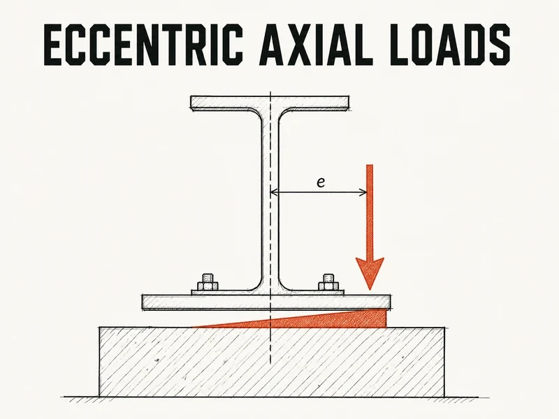
Before you trust P/A plus M/S on a base plate, compare e = M/P with the kern limit of h/6. On a 400 mm plate that cutoff is 66.7 mm, and a column bringing 800 kN down with 60 kNm at the base puts its load 75 mm off centre, already outside it.
Miss that and the check goes wrong quietly. You run the formula, the peak bearing comes out at 10.6 MPa against a 13.8 MPa limit, and you move on. The other edge never gets a look, though the same formula has the concrete there pulling down on the plate. Concrete can’t do that, so the plate lifts and the stress block you just checked doesn’t exist. CSA S16-19 Cl. 25.3.1 is where the kern turns into a design rule.
The kern check - e = M/P against h/6
A moment at the base is just the axial load moved off centre. Divide Mf by Cf and you get that offset, the eccentricity e, and from then on the plate sees one force sitting e away from its middle. For a plate N long in the direction of bending, the elastic stress at the two edges is P/A plus or minus M/S, which for a rectangle tidies up to one line:
$$\sigma = \frac{P}{A}\left(1 \pm \frac{6e}{N}\right)$$You’d expect the formula to be fine as long as the peak passes. But look at the minus sign. The light edge stays in compression only while 6e/N is below 1, which means e can’t go past N/6. That band, a sixth of the depth either side of the centroid for any solid rectangle, is the kern in the direction of bending. Inside it, every point under the plate pushes on the grout. Outside it, the formula starts asking the grout for tension, and grout under a steel plate has nothing to grip.
What S16 lets you assume, and when
Cl. 25.3.1 sends you to CSA A23.3 Cl. 10.8 for the concrete’s bearing resistance, then offers a shortcut. While compression covers the entire plate, you may treat the bearing as uniform over the plate width times N minus 2e. Read elastically, for a rectangular plate bending one way, that condition is the kern check.
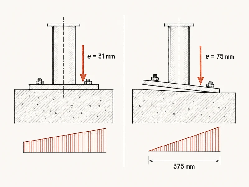
Inside the kern the shortcut is generous. Drop the moment to 25 kNm and e falls to 31 mm, so the elastic peak is 7.3 MPa. The uniform block over the remaining 337 mm of plate works out to only 5.9 MPa, a fifth lower.
Push e past 66.7 mm and the clause no longer applies. The light edge lifts, and with no tension at the interface the pressure gathers into a triangle whose centroid has to sit right under the load. A triangle’s centroid is a third of its length from the heavy edge, so the contact runs three times the distance from the load to that edge. Its peak is twice the average pressure.
Worked example: 800 kN and 60 kNm on a 400 mm plate
Here’s the plate from the top, 400 mm square on a 25 MPa pedestal, bending one way. Cf and Mf have to come from the same factored load combination. Check the one with the least dead load too, because a smaller Cf under the same moment pushes e further out. There’s no confinement credit, and the grout is assumed at least as strong as the concrete. The anchor rods aren’t counted either, which is fair only while nothing pulls up and the triangle can carry Cf within the bearing limit.
Base plate bearing under 800 kN and 60 kNm, 400 mm square plate
Rigid plate, uniaxial moment, no tension at the grout, anchor rods slack, no confinement credit
4 input values\(C_f = 800\) kN, \(M_f = 60\) kNm, \(B \times N = 400 x 400\) mm ...
Step 1: Eccentricity\(e = 75\ \text{mm}\)
Step 2: Kern limit\(66.7\ \text{mm}\)
Step 3: Elastic edge stresses, for comparison\(10.6\ \text{and}\ -0.63\ \text{MPa}\)
Step 4: Contact length of the no-tension triangle\(L = 375\ \text{mm}\)
Step 5: Peak bearing pressure\(q_{max} = 10.7\ \text{MPa}\)
Step 6: Factored bearing resistance per unit area\(13.8\ \text{MPa}\)
At 75 mm the elastic peak lands within 1 percent of the real 10.7 MPa, so this plate survives the mistake. What changed is the contact, because 25 mm of plate has lifted and the S16 shortcut is no longer yours to use.
The same loads go up into the column, where S16-19 Cl. 13.8.2 adds Cf/Cr to 0.85 times the amplified moment ratio for a Class 1 or 2 W-shape, once for each strength case. That’s the factored cousin of P/A plus M/S.
Where the plain formula starts passing plates that fail
The two models drift apart fast past the kern. On this plate the real peak reaches the 13.8 MPa limit at e = 103 mm, about 83 kNm of base moment. The elastic formula still reads 12.8 MPa there, and it keeps passing the plate until about 117 mm. At 90 kNm the formula says 13.4 MPa and a pass, but the triangle is only 263 mm long and peaks at 15.2 MPa, about 10 percent over the limit.
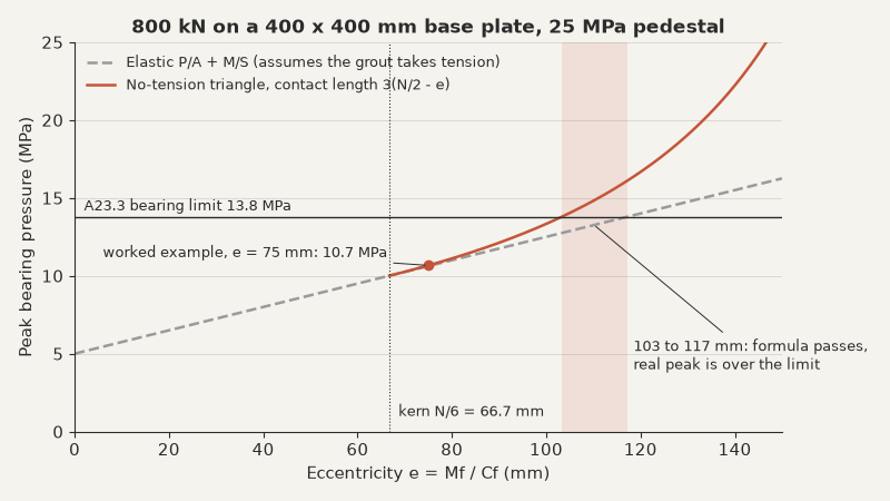
Some limits apply. Past e = 103 mm the triangle can’t carry 800 kN within 13.8 MPa, even with the resultant inside the plate. You then need a bigger plate, or a rod tension design whose bearing block carries Cf plus the rod tension. CSA S16-19 Cl. 25.1 wants uplift carried too, with rods sized to Cl. 25.3.2.1. If the column is part of the seismic force resisting system, the base forces come from S16 capacity design, not from the Mf of a load combination. Both models assume a rigid plate, so check its thickness. Shear transfer (Cl. 25.3.3), rods in shear with tension (Cl. 25.3.4) and pull-out to A23.3 Annex D are separate checks.
Under biaxial moment the full kern is a diamond with half-diagonals of N/6 and B/6, so the two eccentricities share it. A wider pedestal earns up to twice the bearing on the contact area through A23.3 Cl. 10.8.1, which raises the limit line but leaves the kern alone. And on a footing, the plate also moves the punching shear critical section out from the column face.
So the habit is one division before any stress. Inside the kern, P/A plus M/S holds for a rigid plate and the uniform block of Cl. 25.3.1 is available. Outside it, switch to the triangle, because between about 1.5 and 1.75 times the kern on a plate like this one, the plain formula passes bearing that’s overstressed.
The rule stops holding once the rods take tension, since bearing then depends on where the rods sit and how stiff they are. With the plate sorted, run the column above it for your own load, moment and section .