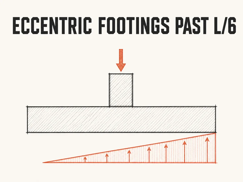
Half the column load can put a footing closer to its bearing limit than the full load did. A 3.0 m square footing carrying 2000 kN straight down sits at 222 kPa against an SLS bearing value of 250 kPa. Take away half the load but move the remaining 1000 kN 600 mm off centre, and the peak climbs to 247 kPa. That’s because past one sixth of the footing length, part of the base stops touching the soil, and the load crowds onto what’s left. NBC 2020 Art. 4.2.4.6 says eccentric loading on a foundation has to be fully investigated.
Why the footing lifts past L/6
Start with the formula everyone learns first. Spread the load over the area, then add and subtract the bending stress, and the edges sit at \(P/A\) times \((1 \pm 6e/L)\). While e is smaller than L/6, both edges push on the soil and the pressure is a trapezoid. At e = L/6 the light edge reaches zero, so the trapezoid becomes a triangle that just spans the footing. That band of e values, a sixth of the length either side of centre, is the kern.
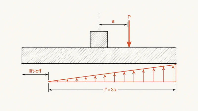
Push e past it and the formula asks the soil at the light edge to pull the footing down. Soil can’t do that, so the footing tips slightly, that edge lifts, and the contact shrinks until the soil’s resultant lines up with the load again. A triangle’s resultant sits a third of its length from the peak, and the load is a distance a = L/2 - e from the loaded edge, so the triangle has to be 3a long:
$$l' = 3\left(\frac{L}{2} - e\right) \qquad q_{max} = \frac{2P}{B\,l'}$$Here B is the footing width at right angles to the eccentricity, and the 2 is there because a triangle’s average is half its peak.
You’d think the plain formula would be close enough, and just past the kern it is. At e = 600 mm on the 3.0 m footing it gives 244 kPa against the true 247 kPa, though it also reports a fictitious 22 kPa of tension at the far edge. The trouble is how fast the two drift apart. At e = 900 mm the triangle is only 1.8 m long and peaks at 370 kPa, while the formula still says 311 kPa, about 16 percent low.
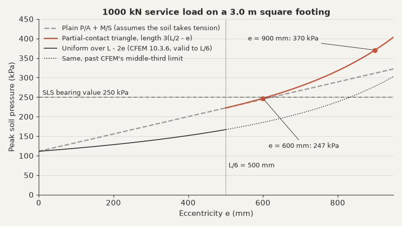
The bottom curve is the geotechnical engineer’s view of the same footing.
Worked example, a 3.0 m footing 600 mm off centre
Take the footing from the opening: 3.0 m square, a 500 mm square column at the centre, 600 kN dead and 400 kN live, and an SLS bearing value of 250 kPa from the geotech. The column’s gravity moment splits between dead and live like the axial load does, so the resultant stays 600 mm off centre in both the service and factored cases. That’s the simple version, where e doesn’t change between combinations. Three checks then read three different pressures off the one footing: the service triangle for SLS, the factored triangle for the concrete, and a uniform pressure over a reduced width for the geotech’s ULS check.
The moment at the column face is the number to watch. Had the same 1000 kN acted at the centre, the factored pressure would be a flat 150 kPa, and the 1.25 m cantilever on each side would carry 117 kN m per metre. The triangle piles its pressure onto the loaded side instead.
Soil pressure on a 3.0 m square footing with e = 600 mm
Rigid footing, linear soil pressure, column loads only (footing and soil weight left out); same e under service and factored loads
6 input values\(B = L = 3.0\) m, \(P_D = 600\) kN, \(P_L = 400\) kN ...
Step 1: Kern limit\(L/6 = 500\ \text{mm} < e = 600\ \text{mm}\)
Step 2: Contact length\(l' = 2.70\ \text{m}\)
Step 3: Service peak pressure\(q_{max} = 247\ \text{kPa}\)
Step 4: Factored load\(P_f = 1350\ \text{kN}\)
Step 5: Factored peak pressure\(q_{f,max} = 333\ \text{kPa}\)
Step 6: Cantilever beyond the column face\(x = 1.25\ \text{m}\)
Step 7: Factored pressure at the column face\(q_f = 179\ \text{kPa}\)
Step 8: Factored moment at the column face\(M_f = 220\ \text{kN m/m}\)
Step 9: Reduced length for the geotech\(L' = 1.80\ \text{m}\)
Step 10: Uniform factored pressure on the reduced footing\(q_{f}' = 250\ \text{kPa}\)
So on column loads alone the footing passes SLS by a hair and carries almost twice the face moment the same load would give if it were centred. The hair doesn’t survive the footing’s own weight. A 500 mm footing adds 108 kN with no moment. That pulls e back to about 540 mm but still lifts the peak to 257 kPa. Ask the geotech whether their 250 kPa is net or gross, and whether it applies to a peak or an average. Either way, the footing sits on a triangle under everyday dead and live load, so in practice you’d lengthen it until the service resultant is back inside the kern.
Which pressure goes to which check
NBC 2020 Art. 4.2.4.1 splits foundation design into limit states. The geotechnical engineer gives you a factored geotechnical resistance for ULS and bearing values for SLS, and you design the concrete to CSA A23.3 with factored loads. Each of those checks reads its own pressure off the same footing, and mixing them up is the usual mistake.
| Check | Loads | Pressure | Compared with |
|---|---|---|---|
| SLS bearing | Service | Triangle past L/6 | Geotech’s SLS bearing value |
| Concrete shear and flexure | Factored | Triangle past L/6 | Factored resistance of the section |
| ULS bearing | Factored | Uniform over L - 2e | Geotech’s factored resistance for that reduced footing |
The SLS value is set by settlement and tilt. A triangle that peaks at the limit on one edge and does nothing on the other is exactly the kind of footing that rotates, so that check is about more than the peak number. For the concrete, CSA A23.3 Cl. 15.2.1 proportions footings for factored loads and the reactions they induce. Cl. 15.2.2 makes linear soil pressure the default, so any other shape needs a soil-structure analysis to back it. Flexure then comes from integrating that pressure beyond the column face (Cl. 15.4.2 and 15.4.3).
CFEM 5 Section 10.3.6 shrinks the side along the eccentricity to L - 2e (CFEM calls that side B) and spreads the factored load uniformly over what’s left. It’s matched to a bearing resistance computed for that smaller footing, so it never gets compared with your triangle. CFEM calls the method reasonable only while the resultant stays in the middle third, e less than B/6. A footing past L/6 under factored loads is outside what the geotech’s own method covers, so they need to hear about it from you.
Wind, property lines and where the triangle stops
The example kept e fixed, so the factored peak was just 1.35 times the service peak, the ratio of factored to service load. That shortcut breaks once wind or seismic sets the moment, because the axial load and the moment no longer scale together. NBC 2020 Sentence 4.1.3.2.(5) takes dead load at 0.9 when it’s the thing holding the footing down. Leave the companion live load out as well, and the wind case has the least axial load and the most moment at the same time.
Suppose the 600 kN m in the example came from wind instead. In 0.9D + 1.4W the footing gets 540 kN of axial load with 840 kN m on it, which puts e at 1.56 m, past the 1.5 m half-width. Before the weight of the footing and the soil over it is counted, the resultant isn’t on the footing at all. That makes it an overturning check, with 0.9 on every dead load that holds the footing down. So recompute e for every combination: 0.9D + 1.4W for overturning, and 1.25D + 1.4W + 0.5L for the peak pressure.
Property line footings get their eccentricity from geometry rather than from a moment. A wall that has to sit at the edge of its footing puts the load at one end, but the soil pushes back near the middle. The gap between the two is a moment, and it has to go somewhere. Usually the floor slab and the footing take it as equal and opposite horizontal forces, tension in the slab and compression at the footing, h apart, so T = C = Pe/h. Take a 150 kN/m service load on a 200 mm wall at the edge of a 1.2 m footing. If the slab holds the footing level, the soil resultant sits at mid-width, 500 mm from the wall centre. With the floor 3.0 m above the footing, as on a basement wall, that’s a 25 kN/m service tie in the slab. Nobody will have designed it unless you factor it and put it on the drawings. You can check bearing and flexure for a wall at one edge , though it leaves the tie to you.
Moments both ways turn the kern into a diamond: divide each eccentricity by the side it runs along, and the two results can add up to no more than one sixth. The base plate post walks through the same kern and triangle on a steel plate. The triangle is a linear pressure on a footing treated as rigid, which is the distribution CSA A23.3 Cl. 15.2.2 accepts without a soil-structure analysis. And the face moment is only one check: one-way shear and punching shear both need the same non-uniform pressure.
The safer line is to size the footing so the service resultant stays inside the kern, and accept partial contact only under a transient factored case such as wind. Seismic brings its own foundation overturning rules in NBC 2020 Art. 4.1.8.16. A footing that sits on a triangle every day settles unevenly and tilts, and no factored check will catch that. Where a wind or seismic case does push e past L/6, give the geotech the eccentricity, not just the load, because their reduced-length method stops being reliable exactly there.