A W250x67 column, 6.0 m tall on a pinned base, fails a 2150 kN axial check at K = 1.0 and passes at K = 0.85, as long as it stays axially loaded. That 0.85 isn’t from a table. It comes from the stiffness of the girders at the top of the column, and in a braced frame that stiffness is worth about 8 percent of the column’s capacity.
Most of us learned K from a US textbook, with two alignment charts and K values of 1.5 or 2 in moment frames. CSA S16 works differently. S16-19 Cl. 10.3 picks K by how the column fails. In-plane bending gets K = 1.0 with the sway carried by the frame analysis, buckling gets K from the end restraint, and S16 has no sway chart at all.
K is the distance between inflection points
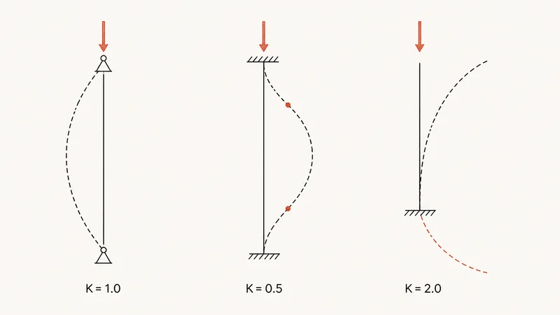
Annex F describes KL as the length of a pin-ended column with the same capacity as the real one. A pin carries no moment, so any point where the buckled column’s curvature flips acts like a pin. That’s an inflection point, and the distance between two of them is the effective length. So the familiar values are sketches you can check, not numbers to memorize.
A column fixed at both ends bows to one side, but its curvature reverses a quarter of the way in from each end, and those are the inflection points. The pin-ended stretch in the middle is half the length, so K is 0.5. A flagpole, fixed at the base and free at the top, bends into a quarter of a sine wave, and you have to mirror it below the base to finish the half-wave. That makes the equivalent pin-ended column twice as long, so K is 2.0, and because capacity falls with the square of KL, the flagpole carries a quarter of the pin-ended load.
In-plane bending or buckling - which K S16 wants
Cl. 10.3.1 sends you to one of two clauses depending on how the member would fail. A beam-column that fails by bending in its own plane uses its actual length, K = 1.0, as long as the frame analysis already includes the sway. A column that fails by buckling, whether straight axial buckling or lateral-torsional buckling out of plane, gets K from the restraint at its ends.
That split is what replaces the sway chart. In a moment frame, S16 asks you to put the sway into the analysis instead of into K. As the frame drifts, the gravity loads act through that sideways movement and add moment, which is the P-Delta effect. You capture it with a second-order analysis, or with the U2 factor that amplifies the sway results of a first-order one. You also add notional lateral loads of 0.005 times the factored gravity load at every storey, which stand in for columns that aren’t quite plumb. The sway then shows up as larger moments and axial loads, and the overall member strength check in Cl. 13.8.2 uses those with K = 1. Use a K of 1.5 as well and you’ve counted the sway twice.
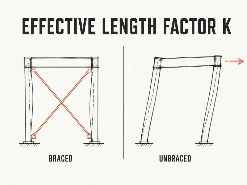
So braced versus unbraced decides how you analyze the frame, not which chart you read. Cl. 13.8.1 calls a frame braced when its bracing makes it at least five times as stiff against sway as the moment connections alone. Anything less is unbraced, even with braces in it.
Annex G for a column in a braced frame
Annex G covers the buckling case in a braced frame, where the column ends can rotate but can’t move sideways. The stiffer the girders are compared with the column, the less the joints rotate and the closer K gets to the fixed-ended 0.5. Flexible girders leave the column close to pin-ended, at 1.0. The annex turns that into a number in four steps.
- At each end of the column, find \(G = \Sigma (I_c/L_c) / \Sigma (I_g/L_g)\), counting only members rigidly connected at that joint and bending in the plane of buckling. I is each member’s moment of inertia and L its length, with c for columns and g for girders.
- At the base, use G = 10 for a column that sits on the footing without a rigid connection, and 1.0 for a base rigidly attached to a properly designed footing (G.4).
- Adjust any girder whose far end is known. For no sway, multiply its I/L by 1.5 when the far end is hinged and by 2.0 when it’s fixed (G.5).
- Solve the G.3 equation for K, or read it off the nomograph in Figure G.1, S16’s alignment chart for sidesway prevented.
Step 3 is where imported habits bite. Many references tell you to halve a girder’s stiffness when its far end is pinned, but that factor belongs to the sway chart, where the girders bend in double curvature. The no-sway nomograph assumes single curvature instead, the girder’s floppiest shape. A hinged far end is actually stiffer than that (3EI/L against 2EI/L), and a fixed one stiffer again, which is where the 1.5 and 2.0 come from.
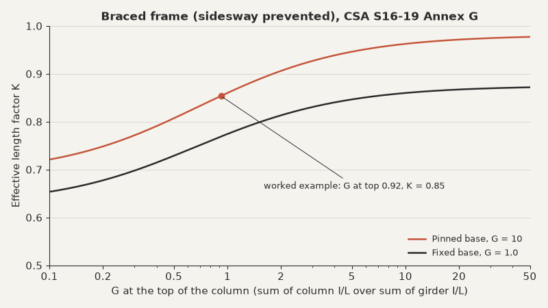
Neither curve gets near 0.5. Even with stiff girders a pinned base keeps K close to 0.7, and a “fixed” base at G = 1.0 stays above about 0.63.
Worked example - a 6.0 m ground-storey column
The column is an interior W250x67 in a two-storey braced building. Cl. 10.3.1 measures a bottom storey from the top of the base plate to the centre of the girders above, which here is 6.0 m. W460x52 girders spanning 9.0 m frame into the flanges with moment connections on both sides, and a W250x67 continues 4.0 m to the roof. The base is a four-bolt plate on a pedestal, not a rigid connection, so G = 10.
Is this a beam-column or an axially loaded column? The spans and loads match on both sides, so the girder moments balance and the column sees almost pure axial load. That makes it a buckling case under Cl. 10.3.3, and Annex G applies about the strong axis, if pattern live load leaves the moment negligible. Struts tied back to the bracing hold the weak axis at third points, so its unbraced length is 2.0 m with K = 1.0.
Effective length and axial resistance of a 6.0 m W250x67 column in a braced frame
Braced frame meeting the Cl. 13.8.1 five-times sway stiffness test, balanced girders so axial load only, 345 MPa steel, n = 1.34; weak-axis struts designed as braces to S16-19 Clause 9 and restraining twist, so Lz = 2.0 m and torsional buckling does not govern
9 input values\(C_f = 2150\) kN, \(L = 6000\) mm, \(F_y = 345\) MPa ...
Step 1: G at the top joint\(G_U = 0.92\)
Step 2: G at the base\(G_L = 10\)
Step 3: K from the Annex G equation\(K = 0.85\)
Step 4: Strong axis at K = 1.0\(C_r = 2050\ \text{kN}\)
Step 5: Strong axis at K = 0.85\(C_r = 2220\ \text{kN}\)
Step 6: Weak axis, braced at third points\(C_r = 2360\ \text{kN}\)
The default K = 1.0 fails this column by 5 percent, and the girders it already has make up the difference. Annex G lifts it from 2050 to 2220 kN, enough to pass as an axially loaded column.
Columns outside a frame - Figure F.1
For an isolated column with no girders to count, Figure F.1 gives six ideal cases, but its theoretical values assume restraints that real connections only approximate. Real fixed ends rotate a little, so S16 raises K in three of the six cases.
| Bottom end | Top end | Theoretical K | S16 recommended K |
|---|---|---|---|
| Fixed | Fixed | 0.5 | 0.65 |
| Fixed | Pinned | 0.7 | 0.80 |
| Pinned | Pinned | 1.0 | 1.0 |
| Fixed | Rotation fixed, free to sway | 1.0 | 1.2 |
| Fixed | Free | 2.0 | 2.0 |
| Pinned | Rotation fixed, free to sway | 2.0 | 2.0 |
Where the nomograph stops paying
That 8 percent only counted because the strong axis governed. Move the weak-axis struts from third points to a single strut at mid-height and the weak-axis length goes to 3.0 m. Its slenderness climbs to 58.8 and Cr drops to 1950 kN, below either strong-axis value.
Now the weak axis governs, and the column fails at 2150 kN whatever K you pick on the strong axis. So check the slenderness on both axes before you refine either one.
The refinement also fades in stocky columns. Below a slenderness of about 30, Cr sits close to the section’s full factored yield capacity, and the difference between K = 0.85 and 1.0 is about 2 percent.
The G.3 equation assumes every column in that part of the frame reaches its critical load at the same time, which G.2 calls conservative. A base whose fixity you can’t pin down, a stepped crane column or a spring support doesn’t fit the nomograph. For those, a buckling analysis in your frame software beats a guessed G, and running the frame with both pinned and fixed bases shows whether the base guess matters. Annex G is informative, so a reviewer may ask about your G, and the slenderness can’t exceed 200 whatever K you use (Cl. 10.4.2.1).
So in a braced frame, the girders you’ve already paid for can buy back the last 5 to 10 percent of a slender column’s capacity, but only on the axis that governs. That stops holding once the column carries real moment, because the overall member check then uses K = 1.0. In this example that’s 2150 kN against 2050 kN, a fail before the moment term is even added, and pattern live load with one span empty is the usual source. The Cl. 13.8.2 check on a column with base moment shows that side, and how much rotational restraint a base or girder connection gives decides whether your G is credible. Then run your own column with its K on each axis .