You’ve built the model, applied the loads, and the deflected shape looks reasonable on screen. The animations are smooth, and there are no obvious instabilities. But a “pretty” model isn’t necessarily a correct one. In finite element analysis (FEA), the quality of your mesh directly dictates the quality of your design forces. A mesh that is adequate for checking drift might be dangerously unconservative for checking shear in a coupling beam.
Effective meshing isn’t just about element size; it’s about understanding how the software calculates results and where the mathematical approximations break down.
The Hierarchy of Convergence
One of the most dangerous misconceptions in FEA is that if the displacements look right, the stresses must be right. This is false. Finite element solvers approximate the solution, and they converge on different results at different rates.
The order of convergence typically flows like this:
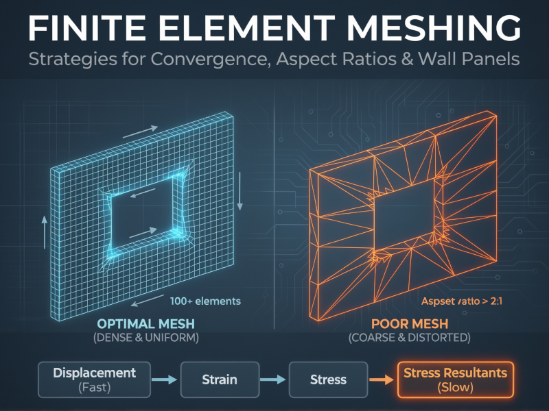
- Displacements (Fastest)
- Strains
- Stresses
- Stress Resultants (Slowest)
Displacements are obtained directly from the solution of the stiffness matrix equations (\(K \Delta = F\)). Strains are derivatives of displacement, and stresses are derived from strains. Finally, stress resultants (moments, shears) are often obtained by integrating stresses.
Each step down this hierarchy introduces another layer of approximation. You can have a mesh that converges perfectly for lateral drift (displacement) but is still 20% off for the bending moment in a shear wall. If you stop refining your mesh as soon as the deflection stabilizes, you might be designing with unconservative internal forces. Always check convergence based on the specific result you are designing for—usually the stress resultants.
Meshing Walls with Openings
Modeling coupled shear walls or walls with openings requires particular attention to mesh density. A coarse mesh might capture the global bending of the core, but it will fail to capture the complex shear flow around openings.
A practical “rule of thumb” for these scenarios is the 100-element rule.
For a single wall panel with an opening (e.g., one storey height of a coupled wall), you should aim for approximately 100 elements within that panel to capture the behavior accurately.
If you mesh a wall panel with only 10 or 20 elements, you effectively stiffen the structure artificially and miss the stress concentrations at the corners of the opening. Starting with a mesh of around 50 elements and refining to 100 or 200 will usually show a significant shift in results. Once you hit that 100-element mark for the panel, further refinement often yields diminishing returns, indicating you’ve reached a stable solution.
Aspect Ratios: The 2:1 Limit
Automated mesh generators are convenient, but they can produce sliver elements—long, thin triangles or rectangles—especially around irregular geometries. These distorted elements are mathematically stiff and can skew the stress distribution.
For structural design purposes, adhere to these limits for element aspect ratios (length-to-width):
- Ideal: 1:1 (perfect squares or equilateral triangles)
- Target: Keep it under 2:1
- Hard Limit: Never exceed 4:1
Elements with aspect ratios greater than 2:1 start to exhibit directional bias. If you have a long rectangular element, it captures gradients well along its length but poorly across its width. In a region with complex stress flow, such as a beam-column joint or a wall pier, this leads to inaccuracies.
If your auto-mesher spits out needle-thin triangles to fit a corner, manually intervene. It is better to have a slightly irregular geometry with good element shapes than exact geometry with poor elements.
Refinement vs. Overkill
More elements equal better answers, right? Not always. There is a difference between necessary refinement and computational overkill.
Consider a cylindrical silo or a tank. Near the base, where the wall is restrained by the foundation, there is a sharp gradient in bending moment. This is a “boundary layer” effect that dies out quickly—typically within a decay length of \(3\sqrt{Rt}\) to \(4\sqrt{Rt}\) (where \(R\) is radius and \(t\) is thickness). In this zone, you need a very fine mesh (e.g., element heights of 4 to 6 inches) to capture the bending spike.
However, halfway up the silo, far from the boundary, the membrane stresses dominate and vary gradually. Refining the mesh to 4 inches here is a waste of time and computational power. It doesn’t improve accuracy; it just bloats the file size.
Similarly, simply adding nodes doesn’t fix a bad model. If you are modeling a pipeline on soil springs and your survey data is spaced at 25 meters, adding finite element nodes every 1 meter between those points adds no new information. You are refining the interpolation, not the data.
Summary Checklist
Before you export your analysis results for design, run through this mental checklist:
- Check the right convergence: Did you verify that moments and shears have converged, not just deflections?
- Count the elements: Does your shear wall panel with openings have at least ~100 elements?
- Inspect the shape: Are there any elements with aspect ratios worse than 2:1 in critical regions?
- Target the refinement: Is your mesh fine where gradients are high (supports, corners) and coarser where stress fields are uniform?