You look up a 15 MPa block with Type S mortar in Table 4 of CSA S304-24, and it gives you 12 MPa. That’s the number most people carry into the beam calc. But a beam is always fully grouted, and the grouted column right next to it says 9 MPa.
That gap matters more than it looks. Take the 85 kNm lintel worked below. With 12 MPa, a 3-course beam looks fine. Switch to the correct 9 MPa and that same beam is over-reinforced, so it needs 4 courses. CSA S304-24 Cl. 12.2 sets the flexure rules this post walks through.
Why beams get the lower f’m
It looks backwards at first. Grout fills the cells, so you’d expect the grouted number to be the higher one. The catch is what each number is measured over. The 12 MPa only counts the thin face shells where the mortar sits. The 9 MPa is spread over the whole solid section, grout and all.
A Clause 12 beam has to be fully grouted, with grout running along every course (Cl. 12.1.3). So you design it on the full section, and the full section goes with 9 MPa. Put 12 on the full 190 mm width and you’ve handed yourself a third more masonry strength than the wall has.
So for any block beam, read the grouted column and move on.
The stress block works like concrete
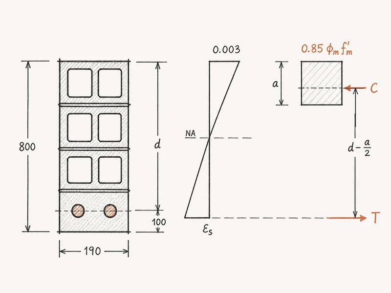
If you’ve designed a concrete beam, you already know the model. The masonry crushes at the top, the steel pulls at the bottom, and a rectangle of uniform stress stands in for the real curved one. Only the numbers change, and here they are.
| Item | Masonry (S304-24) | Clause |
|---|---|---|
| Material factor | \(\phi_m = 0.60\) | 5.3.2.1 |
| Steel factor | \(\phi_s = 0.85\) | 5.3.2.2 |
| Usable compression strain | 0.003 | 12.2.1.2 |
| Stress block | \(0.85\phi_m f'_m\) over \(a = 0.8c\) | 12.2.1.6 |
Balance the bar force against that rectangle and you get the compression depth. Take moments about it and you get the resistance. Those are the only two lines you need:
$$a = \frac{A_s f_y}{\phi_m f'_m b} \qquad M_r = \phi_s A_s f_y \left(d - \frac{a}{2}\right)$$There’s no 0.85 in the first formula because the one on the steel and the one on the stress block cancel out.
Bring two habits over from your old spreadsheet. Use the actual block width, 190 mm, not the nominal 200. And if you learned on S304-14, drop the \(\chi\) factor. That edition cut the stress block to half or 70 percent for beams. The 2024 edition removed it and asks for continuous grout instead.
Turn the balanced limit into one reusable number
You want the steel to yield before the masonry crushes. A beam like that sags and cracks first, so it warns you before it goes. Cl. 12.2.2 makes sure of it by capping how deep the neutral axis can sit. With 400 MPa bars, c can’t go past 0.6d.
Run that limit through the stress block and the balanced steel ratio comes out in one line:
$$\rho_b = 0.00072\, f'_m$$That’s the whole balanced limit for 400 MPa steel. At 9 MPa it comes to 0.65 percent.
From there the balanced moment is \(M_r = K_b b d^2\). Concrete has handbook tables for \(K_b\), but masonry doesn’t. You can check the flexure of your own lintel with your own block and steel, or use the grouted values here.
| Grouted f’m (MPa) | Balanced ratio (percent) | Balanced coefficient (MPa) |
|---|---|---|
| 6 | 0.43 | 1.12 |
| 9 | 0.65 | 1.67 |
| 12 | 0.86 | 2.23 |
| 16 | 1.15 | 2.98 |
Notice both columns grow in step with f’m. That’s why the f’m slip hurts so much. Going from 12 to 9 MPa takes a quarter off every beam’s balanced moment.
Depth comes in 200 mm courses
Masonry doesn’t let you pick any depth you like. The beam goes up one course at a time, and a course is 200 mm. So you jump from 600 to 800 mm with nothing in between.
The bars sit in a bond beam block, a unit with its webs cut down so a bar can lie along the course. Their centre ends up about 100 mm above the bottom, so take d as h minus 100 mm. Knockout depths vary by region, so check with your local supplier.
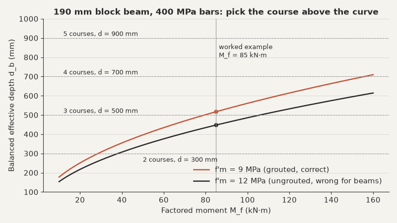
From there it’s simple. Work out the depth the balanced limit needs, then round up to the next full course. A deeper beam with steel sized to the moment stays steel controlled, so the rounding helps. Extra bars, practice minimums and the intermediate bar all push c/d back up, so still check it with every tension bar.
Worked example: an 85 kNm lintel in 190 mm block
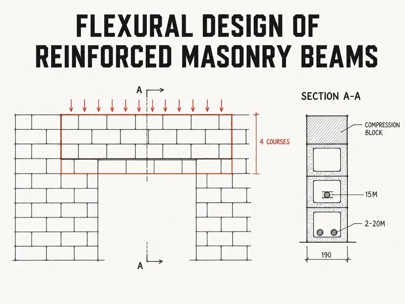
The lintel spans 4.2 m over a loading door in a 200 mm block wall. After arching and self weight, it sees 85 kNm factored. The arching post shows how to get that load. The block is 15 MPa with Type S mortar, so f’m is 9 MPa. The bars are 400 MPa.
The balanced limit wants d of at least 517 mm. Three courses only gives you 500, so the beam goes to four.
Flexural design of an 85 kNm block lintel (CSA S304-24)
Singly reinforced, fully grouted 190 mm block, simple span 4.2 m
4 input values\(M_f = 85\) kNm, \(f'_m = 9\) MPa, \(b = 190\) mm ...
Step 1: Balanced ratio\(\rho_b = 0.00648\)
Step 2: Balanced coefficient\(K_b = 1.674\ \text{MPa}\)
Step 3: Balanced depth\(d_b = 517\ \text{mm}\)
Step 4: Trial steel\(A_s \approx 434\ \text{mm}^2\)
Step 5: Compression block\(a = 234\ \text{mm}\)
Step 6: Moment resistance\(M_r = 119\ \text{kNm}\)
Step 7: Intermediate bar\(\text{1-15M, second course}\)
So the lintel works at four courses with 2-20M bars. Because it’s over 600 mm deep, it also picks up one 15M side bar. It carries 85 kNm against 119 kNm of resistance. If you run it through the linked check, expect a lower number. That tool still follows S304-14, \(\chi\) factor and all.
Where the method breaks
The steel shortcut is only for sizing. \(A_s \approx M_f/(0.7 f_y d)\) assumes the bars work at a lever arm of about 0.82d. The 0.7 is just \(\phi_s\) times that. Always finish with the real \(a\) and \(M_r\). In the example, 2-15M looked close on the shortcut and came up just short on the real check.
Short spans behave differently. Once the span drops below twice the depth, Cl. 12.2.7.2 treats it as a deep beam and shrinks the lever arm. A 1.2 m opening under a 4-course lintel is already there. The shear deformation post explains why plane sections stop holding at that point.
Tall beams pick up extra steel. Over 600 mm deep, Cl. 12.2.6.3 adds a 15M bar partway up the tension side. It also counts when you check the neutral axis, which is why the example’s c/d went from 0.42 to 0.50.
Exterior lintels need a crack check too. Water through cracks is how lintel bars rust, so Cl. 12.2.6.2 caps a crack parameter, and it’s tighter outside than in. The code’s shortcut steel stress of 0.6 fy fails that exterior limit on this lintel. Work the steel stress out from the service moment instead and it passes easily.
Don’t forget minimum steel, 0.2 percent for 400 MPa bars (Cl. 12.2.3.1). There’s an escape hatch where you provide a third more than you need instead. On a lintel it’s rarely worth the paperwork.
Bar sizes come from practice, not the code. Most designers use 15M or bigger, since 10M bends too easily while it’s placed. A 190 mm bond beam holds two bars side by side. If two 20M won’t do it, add a course before you try a second layer.
Then there’s everything flexure doesn’t cover. Shear, bearing and deflection still need their own checks. When software hands you a lintel result, check it against the two lines above. The errors in reinforced concrete design post makes the same case for any design output.
One last thing on editions. NBC 2020 still references S304-14, so confirm which one your jurisdiction has adopted before you cite S304-24.
Three rules for your next lintel
- Read the grouted column of Table 4 for every beam. For a 15 MPa block in Type S mortar, that’s 9 MPa.
- Work out \(\rho_b = 0.00072 f'_m\) and the balanced depth, then round up to a full course.
- Size the steel with the shortcut, but sign off on the real \(M_r\) and \(c/d\) from Cl. 12.2.