You’ve built a complex model, the render looks fantastic, and the software spits out pages of data. But deep down, there’s a nagging question: can I really trust these numbers?
With today’s powerful software, it’s dangerously easy to become a software operator instead of a master modeler. An ineffective model can produce a false sense of precision, hiding incorrect load paths or dangerously underestimating stresses. As engineers, our duty of care under bodies like PEO and EGBC demands we use these tools responsibly.
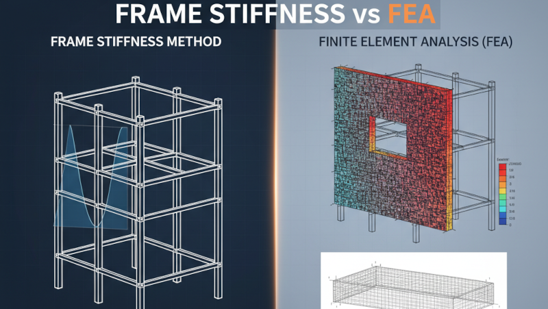
This post gets back to the fundamentals behind the two primary engines in our digital toolbox: the Frame Stiffness Method (FSM) and the Finite Element Method (FEM). We’ll explore when to trust your frame analysis implicitly and when you need to roll up your sleeves and scrutinize your finite element mesh.
Who should read this: EITs building foundational knowledge, intermediate engineers looking to solidify their understanding, and senior leads aiming to refine their team’s modelling standards.
The Frame Stiffness Method (FSM)
For most of us, the Frame Stiffness Method is the workhorse behind our day-to-day analysis of beams, columns, and braces. It’s the engine in programs like SAP2000, S-FRAME, and ETABS when you’re dealing with frame elements.
It works by idealizing our structure as a discrete system—a collection of 1D line elements (members) connected at discrete points (joints). The software builds a global stiffness matrix, solves for joint displacements under your applied loads, and then works backward to find the forces in each member.
But how does the software know how a member behaves between the joints? That’s where shape functions come in.
Shape Functions
Your software assumes every beam-column element deforms according to a prescribed mathematical recipe, its shape functions. For a standard 2D beam-column element, these are:
- Axial Displacement: Assumed to be linear from one end to the other.
- Transverse (Bending) Displacement: Assumed to follow a cubic polynomial (\(w(x) = C_0 + C_1x + C_2x^2 + C_3x^3\)).
This might seem like a dry, academic detail, but it’s the most important concept to grasp. Why? Because that cubic polynomial is special. Its derivatives perfectly describe the shear and moment within a beam segment that is only loaded at its ends: the second derivative (related to moment) is linear, and the third derivative (related to shear) is constant.
Why this matters: The Frame Stiffness Method provides the theoretically exact solution (relative to engineering beam theory) for a prismatic member subjected only to concentrated loads and moments at its joints. The assumed shape function perfectly matches the real-world behaviour. Your software isn’t guessing—it’s giving you the answer for the idealized problem you’ve defined.
When Your Frame Model Gives You the Exact Answer
This “exactness” is powerful. If you’re modelling a structure where loads are applied only at the joints—a typical truss, a braced frame with loads at floor levels, or a moment frame with column point loads—your analysis is precise.
Common Mistake: Adding unnecessary nodes to “refine” the model. A classic cautionary tale involves an engineer modeling a buried pipeline with measured settlements imposed at 20-meter intervals. Concerned about the spacing, they added more nodes between the measurement points and were surprised when the results didn’t change at all. They mistook this for convergence. In reality, the software already had the exact solution for a beam with those point loads; adding intermediate nodes doesn’t change the mathematically perfect cubic curve between them. The real error was modeling a continuous soil load as a series of widely spaced point loads.
For distributed member loads, your software uses superposition. It calculates the fixed-end forces, applies the opposite to the joints, solves the “exact” point-loaded global model, and adds the results. For standard load types, this process is also exact.
The Finite Element Method (FEM)
FSM is fantastic for skeletal structures. But what about shear walls, slabs, complex connections, or foundations? For these, we need to model the behaviour of a continuum, and that’s the domain of the Finite Element Method.
FEM (or FEA for analysis) works by breaking a continuous surface or solid into a collection of small, simple pieces called “finite elements” (like triangles or quadrilaterals) connected at nodes.
FEM is (Almost) Always an Approximation
This is the fundamental shift in thinking you need to make. Unlike the specific cases in FSM, a solution from an FEA is an approximation. Its accuracy depends entirely on two things:
- The shape functions of the elements you choose.
- The size and arrangement of those elements (your mesh).
Instead of FSM’s specific cubic polynomial, a basic FEM element like a Constant Strain Triangle (CST) uses a simple linear polynomial to approximate displacement. This means it assumes strain (and therefore stress) is constant across the entire element. It’s a poor choice for capturing bending unless you use an incredibly fine mesh.
Mesh rule of thumb: Your FEA solution is only as good as your mesh. You can’t just accept the default auto-mesh and move on. You must perform checks to ensure your results have converged to an acceptable answer. For specific strategies on aspect ratios and density, check out our guide on effective finite element meshing.
A Practical Guide to Getting Good FEA Results
If FEA is an approximation, how do we know our approximation is good enough? The answer is convergence.
Always Check for Convergence
Convergence is the process of refining your mesh until the solution stops changing significantly. It’s non-negotiable for any serious FEA.
Here’s a simple workflow:
- Build your model with a reasonably coarse mesh.
- Run the analysis and record a key result you care about (e.g., maximum deflection, or peak stress at a corner).
- Refine the mesh. A good rule of thumb is to halve the element size in the area of interest.
- Run the analysis again and compare the result.
- Repeat until the percentage change in your result is small enough for your engineering judgment.
Displacements Converge Faster Than Stresses
Here’s a critical point that trips up many engineers: different results converge at different rates. The general hierarchy, from fastest and most accurate to slowest and least accurate, is:
- Displacements
- Strains & Stresses (which are derived from the derivatives of the displacement field)
Watch for: Just because your deflections have converged doesn’t mean your stresses have. A mesh that accurately predicts building drift —a critical serviceability limit state— might be dangerously coarse for predicting the peak stresses needed to design reinforcement around an opening in a shear wall. If stress is what you need for your design (as per CSA A23.3, for example), you need a much finer mesh in that specific region.
Meshing Best Practices & Common Pitfalls
- Aspect Ratios: Keep your elements as square-like as possible. Aim for an aspect ratio (longest side / shortest side) of less than 3:1. Long, skinny elements give biased, inaccurate results.
- Stress Gradients: Use a finer mesh where you expect stresses to change rapidly: re-entrant corners, around openings, near point loads, and at supports.
- Model Consistently: Remember the cautionary tale of the concrete silo. The engineer modeled the curved wall with flat shell elements (a reasonable simplification) but then applied the true, continuous radial pressure. This inconsistency introduced large, artificial bending moments at the facets that don’t exist in reality, leading to a 200%+ error in stress. A consistent model would have also simplified the load into point forces at the nodes.
Common pitfall: Don’t Chase Singularities. In FEA, a sharp re-entrant corner (like the inside corner of an L-shaped wall opening) is a stress singularity. Mathematically, the stress at that infinitesimal point is infinite. If you keep refining your mesh at that exact point, the stress value will keep increasing and will never “converge”. This is a mathematical artifact of the model, not a physical reality (as real materials would yield and redistribute the stress). Instead of chasing an infinite number, focus on the stress a small, realistic distance away from the corner to inform your design.
Advanced Considerations in Canadian Practice
Applying these methods effectively goes beyond the theory. Here are a few common issues we face in Canadian practice.
Handling Concrete Cracking (CSA A23.3)
A linear elastic analysis of a concrete structure using gross section properties will always overestimate stiffness. This leads to underestimated deflections and an incorrect distribution of moments. CSA A23.3, Clause 9.5, is clear that analysis must account for the effects of cracking.
In Practice vs. In Code: While a full nonlinear analysis is rarely practical for building design, the code demands we do better than using gross properties. The common-sense approach is to use effective or “cracked” section properties. Applying stiffness modifiers to your members and shells (e.g., \(0.35I_g\) for beams, \(0.70I_g\) for columns, \(0.25I_g\) for slabs) is a pragmatic way to get a more realistic distribution of forces and a better estimate of deflections.
Including Shear Deformations (CSA S16)
Standard FSM beam elements (based on Euler-Bernoulli theory) neglect shear deformations. This is fine for slender members, but for deep beams, link beams, or plate girders, shear can be a significant part of the total deflection. Most software allows you to include shear deformations (using Timoshenko beam theory). For steel members, CSA S16 provides specific guidance on calculating the required shear area (\(A_v\)).
P-Δ Effects
First-order analysis neglects secondary moments from axial loads acting on a displaced structure (P-Δ and P-δ effects). CSA S16 mandates that stability effects be considered. While amplified first-order methods exist, a direct second-order analysis is the preferred and more robust method available in all modern software. Don’t turn it off unless you have a very good reason.
Choosing the Right Modelling Approach
The mark of an effective modeler isn’t the ability to generate a pretty render, but the discipline to build the simplest possible model that accurately captures the essential structural behavior. It’s a discipline that involves actively challenging your model’s assumptions to gain real confidence in its predictions.
- For typical frame structures, the Frame Stiffness Method is efficient and often theoretically exact for the member forces you need for design. Trust it.
- For walls, slabs, and complex geometries, the Finite Element Method is a powerful, necessary tool. But it’s an approximation that demands your engineering judgment to verify its accuracy through careful meshing and convergence checks.
The software is a powerful but fallible tool. Our professional duty is to use it with competence and diligence, always using the analysis to augment, not replace, our engineering judgment.
Your Next Steps:
- The next time you model a simple frame, take a moment to identify why FSM is giving you an exact solution for the joint-loaded case.
- On your next FEA model, perform a quick convergence study on one critical area. Halve the mesh size and see how much your peak stress changes. Is it what you expected?
- Pull up a past concrete model and check if you accounted for cracking in your stiffness assumptions as required by CSA A23.3.
It’s often worth revisiting past models where results felt “too clean”—many of the most instructive errors come down to a simple meshing choice or an assumption about stiffness that didn’t quite match reality.