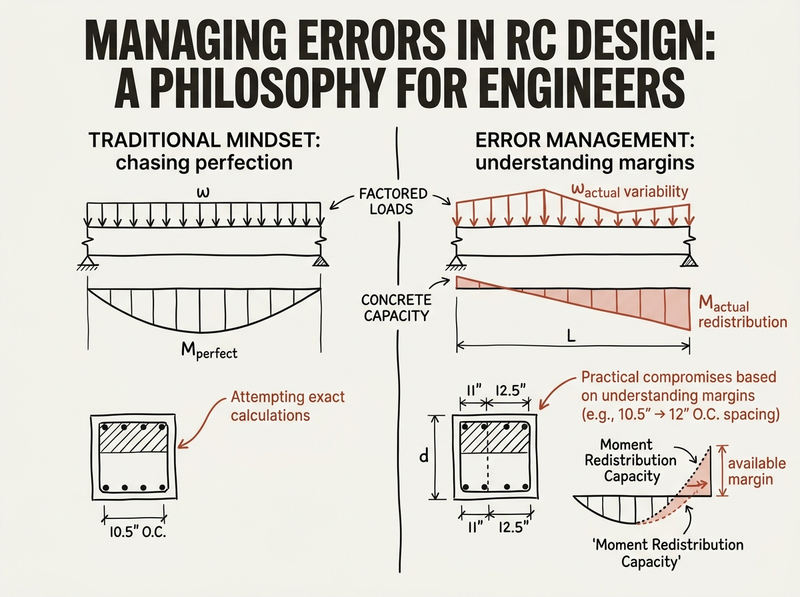
The best structural engineers aren’t the ones who get everything right. They’re the ones who understand their errors and manage them.
Reinforced concrete design is inherently uncertain. Our codes, equations, and construction processes all contain embedded variability, and the engineer who grasps this makes better decisions than one who follows equations hoping the numbers will cover them.
What RC Design Numbers Actually Mean
Most of us learned reinforced concrete design by mastering equations. Calculate the moment, find the required steel area, check the capacity. If the numbers work, you’re done.
But there’s a gap between competent and confident, and it’s this: understanding what those numbers actually mean.
Engineering design isn’t about following the code and “trying to do it right.” It’s about understanding how big your errors are and what the consequences of those errors might be.
Take a swing stage with a cable rated to ten times the expected load. The cable looks thin-but if your calculations are off by 3%, 5%, even 10%, you still have a factor of safety of 9. That’s plenty of margin.
Now think about your reinforced concrete slab. Where are the errors? How much margin do you actually have? If you can’t answer these questions, you’re relying on the code to protect you without knowing how it protects you.
Where Errors Enter Your Reinforced Concrete Design
Errors come in at every stage. Accepting this is what sharpens your judgment.
In the design phase
The code equations themselves are approximations:
- Plane sections remain plane is an assumption, not a physical law. We use it because calculating any other way isn’t practical-real strain distributions may differ.
- The equivalent rectangular stress block (CSA A23.3 Cl.10.1.7) replaces the actual curvilinear concrete stress distribution with a rectangle for mathematical convenience. There’s error baked into \(\alpha_1\) and \(\beta_1\).
- Material properties like modulus of rupture (\(f_r = 0.6\lambda\sqrt{f'_c}\)) are empirical relationships, not exact values.
Rather than memorizing \(0.6\sqrt{f'_c}\), think about it practically. For 25 MPa concrete, \(\sqrt{25} = 5\), so \(f_r \approx 3\) MPa. For 35 MPa, \(\sqrt{36} \approx 6\), so \(f_r \approx 3.6\) MPa. Numbers you can carry in your head.
Development length equations are empirical relationships too, so you can check the required development length for your bar and see what that approximation gives.
In the field
Variability compounds here:
- Modern batching is accurate, but not perfect
- A two-hour truck ride from the batch plant affects workability and potentially strength
- Pumping, wheelbarrow, crane bucket-each introduces different handling
- Vibration quality varies with the placer
- Temperature, moisture, and timing all affect curing
- Rebar spacing: do you really expect exactly 12" on centre? You’ll get 11.5" or 12.5"
And then there’s stripping. The contractor says they can’t wait seven days-is it okay to strip after five? These decisions happen whether you’re involved or not.
How CSA A23.3 Safety Factors Build In Margin
CSA A23.3’s limit states design framework builds in margins through material resistance factors and load factors.
For materials:
- Steel (\(\phi_s = 0.85\)): Nominal capacity reduced by 15%
- Concrete (\(\phi_c = 0.65\)): Nominal capacity reduced by 35%
Why the difference? Steel production is tightly controlled with excellent quality assurance. Concrete involves batching, mixing, placing, vibrating, and curing-all on site, all subject to variability. The bigger reduction for concrete reflects that uncertainty.
For loads:
- Dead load factor: 1.25 - Self-weight is well-known
- Live load factor: 1.5 - Actual occupancy loads are harder to predict
These factors aren’t arbitrary. They’re based on probability and the consequences of exceeding capacity. But knowing that they exist isn’t enough. You need to know how much margin they provide for your specific situation.
When you factor up loads and factor down capacities, you’re not “being safe”-you’re applying a probabilistic framework that accounts for variability inherent in the system. Understanding this distinction matters when you start making judgment calls.
Rebar Spacing Changes: How Much Margin Do You Have?
The contractor comes to you:
“The drawings call for 10.5” rebar spacing. Can we do 12" instead? It’s much easier to place."
That’s a 15% reduction in steel area. Can you allow it?
The wrong answer: “No, the drawings say 10.5 inches.”
The right answer requires asking: What’s my actual margin here?
Consider:
- Did you use conservative assumptions in your load estimate?
- Is this a simply supported span or continuous (where there’s redistribution capacity)?
- What’s driving the rebar quantity-flexure, minimum steel requirements, or crack control?
- Is the concrete strength you specified conservative relative to what they’ll actually deliver?
If you understand your embedded margins, you can make an informed decision. Maybe you designed with 35 MPa specified strength, but typical delivered concrete runs 40-45 MPa. Maybe your live load assumption was conservative. Maybe the slab is continuous.
A good engineer doesn’t just follow equations-they understand how conservative those equations are in their specific application. That understanding is what enables practical compromise without compromising safety.
Moment Redistribution and Redundancy in RC Design
Reinforced concrete naturally lends itself to continuous, redundant systems in a way that steel or timber framing often doesn’t. When you design continuous spans-slabs over multiple supports, multi-bay frames-load can redistribute.
If one part of your structure is slightly overloaded, other parts can help carry it. Multiple load paths to the foundation.
Compare this to a simply supported wood joist. If it’s overstressed, nothing else helps it (other than maybe some bridging). Failure of one member means local failure.
In continuous reinforced concrete, moment redistribution is built into the physics. If the negative moment region yields slightly, moment shifts to the positive region. CSA A23.3 Cl. 9.2.4 explicitly permits up to 20% redistribution in qualifying sections, provided the section has sufficient ductility - this isn’t a workaround, it’s a designed-in capacity. This plastic behaviour is RC’s structural advantage, but only if you understand it and design for it.
When your colleague designs the same slab with slightly different steel quantities, you might both be right. In RC design, there’s often a range of acceptable solutions. The question is whether you understand your margin within that range.
RC Design Margin Checklist
Before design
What are the load assumptions, and how confident am I?
- Dead load: Concrete self-weight is well-known. Finishes and mechanical allowances are less certain.
- Live load: Code minimums may be conservative for your actual use case.
What concrete strength will actually be delivered?
- In practice, concrete is often delivered 10-20% above specified strength - contractors overbatch to protect against test failures.
Is the structure statically determinate or indeterminate?
- Indeterminate structures have built-in redistribution capacity.
During design
How conservative are the code equations I’m using?
- The equivalent stress block is an approximation. \(\alpha_1 \approx 0.8\) and \(\beta_1 \approx 0.9\) for typical concrete strengths.
Am I designing to minimum requirements or optimal requirements?
- Sometimes minimum steel governs. That’s built-in margin.
What’s the sensitivity of my design to small changes?
- If going from 10.5" to 12" spacing causes a 15% reduction in capacity, what does that mean relative to demand?
During construction
What construction tolerances are realistic?
- CSA A23.1 specifies placement tolerances. Are they being met?
What can go wrong, and what’s the consequence?
- Rebar shifted slightly low reduces effective depth-but by how much?
Worked Example: Continuous Slab with CSA A23.3
You’re sizing a continuous one-way slab. Analysis gives you the required steel area for the negative moment region over the supports. You select 15M bars at 200 mm spacing.
Now ask:
- Continuous span means redistribution capacity-that’s a buffer
- Factored loads \(1.25D + 1.5L\)-margin in the load estimate
- \(\phi_c = 0.65\) means you’re using 65% of the concrete’s capacity
- \(\phi_s = 0.85\) means you’re using 85% of the steel’s capacity
- The contractor will likely deliver 40 MPa concrete even though you specified 35 MPa
With those margins stacked, you have real confidence in your design. And if the ironworker places rebar at 225 mm instead of 200 mm in some locations? You know you still have room.
That’s error management in practice.
How This Changes Your Practice
This mindset changes how you work. You stop sweating decimal places when field variability is an order of magnitude larger than calculation precision. When a contractor calls with a question, you can distinguish what’s genuinely load-critical from what has room to move. Design details lean toward constructability - a heavier design built well beats an optimized one executed poorly.
Where to Start
Pick one recent RC design. Walk through the error sources-load assumptions, material factors, construction tolerances. Where are your margins?
Look at the code equations you use regularly. Do you understand the approximations in them? The equivalent stress block, the shear provisions, the development length equations: each has built-in conservatism.
Next time you get a contractor question, resist the urge to immediately say no. Ask yourself: what’s my actual margin here? In most cases, you’ll find the code has already built you more room than you realized.