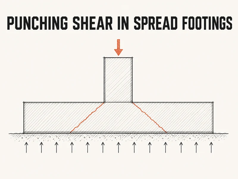
A 3.0 m square footing under 2750 kN factored comes out at 650 mm with the usual hand calc, which takes the whole column load as the shear and ignores the size effect. Credit the soil under the column and the check even looks comfortable, at a ratio of 0.85. It isn’t, though. Put in the size effect factor and that same footing comes up about 1 percent short, so the answer is 700 mm. CSA A23.3-24 Cl. 13.3.4.3 is the clause that does it.
Thick concrete can’t carry as much shear stress as thin concrete, because the diagonal crack that fails it opens wider before the aggregate on either side can lock together. A footing is about as thick as concrete gets in an ordinary building, so that’s where the reduction bites first.
Where the plug punches out
Picture the column trying to push a plug of concrete out through the bottom of the footing. The crack runs down and outward at roughly 45 degrees, so the plug is a truncated pyramid. The code swaps that sloped surface for a vertical one set d/2 out from each column face (CSA A23.3-24 Cl. 13.3.3.1). Here d is the effective depth to the bottom bars, and with two layers stacked at right angles, punching uses their average, the line where they touch. The dashed square in the sketch is that section, and the vertical dashed line is the one-way shear section, which comes back at the end.
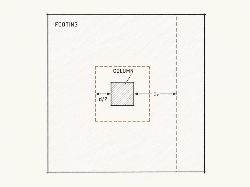
For a square column of side c, that perimeter is \(b_o = 4(c + d)\) long. The soil pushes up over the whole footing, but the pressure inside the perimeter only pushes the plug back up against the column, so it never crosses the crack. The punching shear is just the pressure on the shaded ring outside:
$$V_f = q_f \left[ A - (c + d)^2 \right]$$Here \(q_f\) is the net factored soil pressure, the column load spread over the footing’s plan area \(A\). Footing and backfill weight push down as hard as the soil pushes back under them, so they drop out. Subtracting the inner square is free resistance, and on this footing it’s worth one 50 mm step of thickness.
How much stress the concrete can carry on that perimeter comes from three equations in Cl. 13.3.4.1, and you take the smallest. All three scale with \(\lambda \phi_c \sqrt{f'_c}\), where \(\phi_c\) is 0.65 and \(\lambda\) is 1.0 for normal-density concrete.
| Limit | Coefficient | What it covers |
|---|---|---|
| Eq. 13.5 | \(0.19(1 + 2/\beta_c)\) | Long, narrow columns (\(\beta_c\) is the column’s long side over its short side) |
| Eq. 13.6 | \(0.19 + \alpha_s d / b_o\) | Edge and corner columns (\(\alpha_s\) is 4 interior, 3 edge, 2 corner), or a large column on a thin footing |
| Eq. 13.7 | 0.38 | The cap for everything else |
For a square column the first gives 0.57, and the second stays above 0.38 until the perimeter is about 21 times d. So a square interior column almost always lands on the flat 0.38, or 1.24 MPa at 25 MPa. A column twice as long as it is wide, or an edge or corner column, can change that, so recheck all three once you know d.
Then the size effect factor goes on top of whichever one governs. It’s the lesser of 1 and 1300/(1000 + d), with d in mm, so it starts to bite once d passes 300 mm. At d = 550 mm it’s 0.84, which means a footing that deep loses 16 percent of its punching resistance. That’s about the same as dropping the concrete from 25 MPa to 18 MPa.
Worked example, a 3.0 m footing under 2750 kN
Take a 500 mm square interior column carrying 2750 kN factored onto a 3.0 m square footing, in 25 MPa normal-density concrete with 20 mm aggregate. The bottom mat is 25M each way, fy = 400 MPa, at 75 mm cover. Because the two directions stack, their contact line sits 100 mm above the bottom, so d is h minus 100 mm. You can check whether your own footing thickness passes with the same inputs.
The awkward part is that d sits on both sides, because a deeper footing has a longer perimeter and a smaller shaded ring. Set demand equal to resistance and you get a quadratic in d, with \(v_c\) the governing stress from the table:
$$(4v_c + q_f)\, d^2 + (4v_c + 2q_f)\, c\, d - q_f (A - c^2) = 0$$The size effect factor sits inside \(v_c\) and depends on d too, so guess d, solve, then update the factor once.
Punching shear thickness for a 3.0 m square footing (CSA A23.3-24)
Concentric load, uniform soil pressure, no shear reinforcement; d = h - 100 mm for two layers of 25M (fy = 400 MPa) at 75 mm cover
6 input values\(P_f = 2750\) kN, \(B = 3.0\) m, \(c = 500\) mm ...
Step 1: Factored soil pressure\(q_f = 306\ \text{kPa}\)
Step 2: Basic punching stress, Eq. 13.7\(v_c = 1.24\ \text{MPa}\)
Step 3: Try h = 650 mm, size effect factor\(\lambda_s = 0.839\)
Step 4: Try h = 650 mm, resistance\(V_r = 2390\ \text{kN}\)
Step 5: Try h = 650 mm, demand\(V_f = 2410\ \text{kN}\)
Step 6: Required d from the quadratic\(d = 0.553\ \text{m}\)
Step 7: Use h = 700 mm, d = 600 mm\(V_r = 2650\ \text{kN}\)
Step 8: Use h = 700 mm, demand\(V_f = 2380\ \text{kN}\)
Drop the size effect factor and that 650 mm footing reads 0.85, which is why the old answer feels safe. With the factor it reads 1.01, and a 1 percent overrun is still a fail, because the resistance factors already hold the margin you’d be tempted to spend. So use 700 mm, at a ratio of 0.90.
The usual shortcut of taking the whole column load as the shear, inner square and all, is always conservative. With the size effect in, it fails 700 mm too, so at 50 mm steps you’d pour 750 mm, about 7 percent more concrete than the check needs.
Why the resistance jumps at 725 mm
There’s a catch in the other direction. Cl. 13.3.4.4 lets you take the size effect factor as 1.0 for a footing when the point of zero shear sits less than 2d from the column face. Under uniform pressure on a concentric footing, shear dies out at the footing edge, so this post reads that distance as the overhang. The clause doesn’t say it in those words, so confirm your reviewer reads it the same way.
A short, deep cantilever doesn’t really work as a beam, because it carries the soil load by arching straight to the support, the way a masonry wall carries itself over an opening. Arching doesn’t rely on a tight diagonal crack, so the size effect drops out.
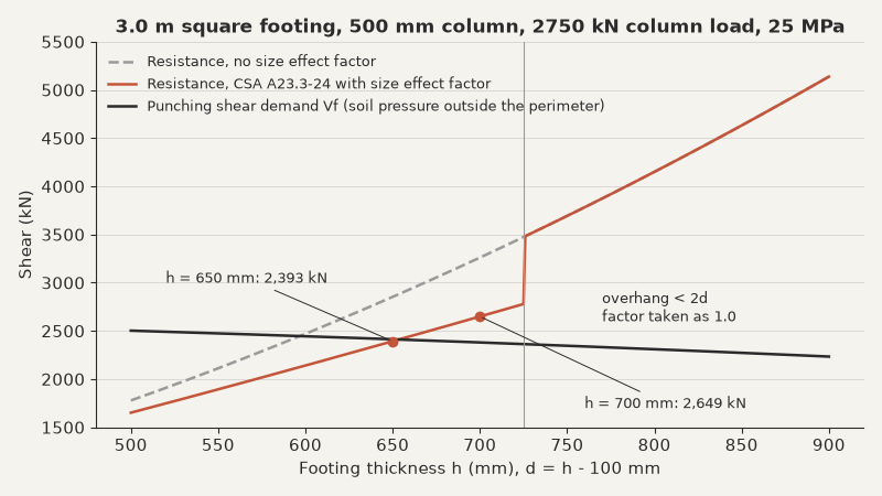
So resistance doesn’t climb smoothly with thickness. It jumps at 725 mm. With a 1250 mm overhang the exemption starts at d over 625 mm, or h over 725 mm, which neither trial thickness here reaches, so the full 16 percent loss stays in for both.
One-way shear, and where the check stops
Could one-way shear sneak in ahead of punching? Not on this footing. Treat the footing as a wide beam cantilevering off the column face, with the critical section dv out from the face. Here dv, the effective shear depth, is the larger of 0.9d and 0.72h. The resistance is \(V_c = \phi_c \lambda \beta \sqrt{f'_c}\, b_w d_v\), and beta, the share of shear the cracked concrete carries, is where people go wrong.
Cl. 11.3.6.2 allows the easy 0.21 only when the footing is 350 mm thick or less or the overhang is under 2dv. Even then, the bars must be 500 MPa or less and the aggregate 14 mm or more. Otherwise, for a footing with no stirrups, 400 MPa bars and 20 mm aggregate, Cl. 11.3.6.3 b) gives 230/(1000 + dv), which is a good deal smaller. When steel across a plane carries the shear instead, that’s shear friction.
One-way shear uses each layer’s own d rather than the contact line. The upper layer governs because it sits higher, at d = 587.5 mm and dv = 529 mm. The overhang is more than 2dv, so beta drops to 0.150 instead of 0.21. Run that across the full 3.0 m width beyond the critical section and the footing carries 776 kN against 661 kN of demand. That’s a ratio of 0.85, so punching still governs. A long rectangular footing is different, because the cantilever in its long direction picks up more of the soil load, so run both directions every time.
Everything above assumes a concentric load on an interior column, and each way of leaving that assumption changes the check. A column moment adds shear stress to one side of the perimeter (Cl. 13.3.5). A column on a property line loses one side of the perimeter, or two at a corner, with \(\alpha_s\) dropping to 3 or 2. A steel column on a base plate moves the critical section out from the column face (Cl. 15.5.2). Bars stronger than 400 MPa switch the one-way beta to Eq. 11.9b, which gives 203/(1000 + dv) at 500 MPa. The size effect itself isn’t new in 2024, since A23.3-19 had the same factor and the same 2d exemption, and what 2024 added is the bar and aggregate limit on beta = 0.21. This is also a shear check only, so flexure and minimum steel (Cl. 15.4), bar development and bearing at the column still decide whether 700 mm goes on the drawing.
For a concentric footing, then, the punching check comes down to three moves: subtract the inner square, apply the size effect factor, and compare the overhang with 2d before you accept the loss. That holds while the soil pressure stays uniform. Once a column moment or a property line makes it lopsided, the stress around the perimeter isn’t uniform either, and the quadratic above stops being the answer.