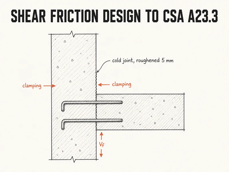
A 200 mm slab cast against a hardened shear wall, carrying 2000 kN of factored shear over 5 m, needs 20M @ 225 dowels across the joint to CSA A23.3-24 Cl. 11.5 if the wall face is roughened to 5 mm. If the face is left smooth, the same joint needs 20M @ 125. If you switch to the alternative equation in Cl. 11.5.3, it drops to 20M @ 375.
The joint condition you assume moves the steel by a factor of three. Below is where each number comes from, and why the monolithic case people often reach for on this joint doesn’t apply.
Shear friction in one equation
CSA A23.3-24 Cl. 11.5.1 assumes a crack along the shear plane and resists slip with cohesion plus friction. The friction comes from the bars that cross the crack. As the rough faces slide, they ride up over each other and pry the crack open. The bars resist that opening in tension, and the tension clamps the faces together.
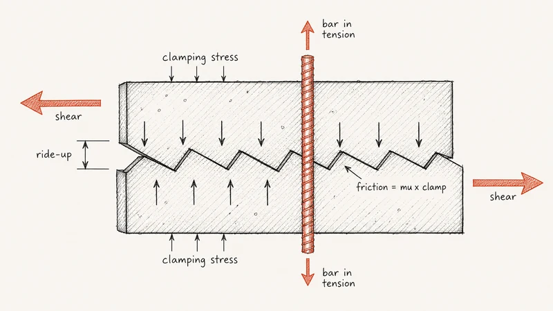
The factored shear stress resistance is Eq. 11.25:
$$v_r = \lambda \phi_c (c + \mu \sigma) + \phi_s \rho_v f_y \cos \alpha_f$$with the clamping stress from Eq. 11.27 (Cl. 11.5.4):
$$\sigma = \rho_v f_y \sin \alpha_f + \frac{N}{A_g}, \qquad \rho_v = \frac{A_{vf}}{A_{cv}}$$Here \(c\) is the cohesion stress, \(\mu\) the friction coefficient, \(A_{vf}\) the bar area crossing the plane, \(A_{cv}\) the plane area, \(\alpha_f\) the bar angle to the plane and \(N\) the unfactored permanent load across the plane. With bars perpendicular to the joint (\(\alpha_f = 90^\circ\)) and no permanent compression, it collapses to
$$v_r = \lambda \phi_c (c + \mu \rho_v f_y) \le 0.25 \phi_c f'_c$$The \(\phi_s\) term drops out at 90 degrees, so \(f_y\) enters unfactored and \(\phi_c = 0.65\) (Cl. 8.4.2) carries the margin, the same way resistance factors build margin into RC design everywhere else in A23.3. Practically, this means you solve for \(\sigma\) and divide by plain \(f_y\), not \(0.85 f_y\).
Pick c and mu from the joint you’ll actually get
Cl. 11.5.2 sets four cases:
| Case | Interface | \(c\) (MPa) | \(\mu\) |
|---|---|---|---|
| (a) | Against hardened concrete, clean, not intentionally roughened | 0.25 | 0.60 |
| (b) | Against hardened concrete, clean, roughened to at least 5 mm full amplitude | 0.50 | 1.00 |
| (c) | Placed monolithically | 1.00 | 1.40 |
| (d) | Anchored to as-rolled steel by headed studs or bars | 0.00 | 0.60 |
A slab that’s cast after the wall is case (a) or (b), whatever the analysis model assumes. Monolithic only applies when both sides of the plane really go in the same pour, like a crack plane inside a corbel or a slab-to-beam joint placed together. Retrofit work, where new concrete goes against existing, is always (a) or (b).
Case (b) only counts if someone builds it. Sandblasting alone usually won’t reach a 5 mm amplitude, so confirm the method with the contractor; chipping and hydrodemolition are the usual routes. Write “roughen to 5 mm full amplitude, clean, saturated surface dry before placing” on the drawing next to the joint, or design to case (a).
Steps 1 to 4: from shear force to bar area
- Plane area. \(A_{cv}\) is the contact area: slab thickness times joint length for a slab-to-wall joint.
- Factored shear stress. \(v_f = V_f / A_{cv}\).
- Required clamping stress. Set \(v_r = v_f\) and solve:
- Steel and cap. \(\rho_v = \sigma / f_y\), \(A_{vf} = \rho_v A_{cv}\), then confirm \(\lambda \phi_c (c + \mu \sigma) \le 0.25 \phi_c f'_c\).
For roughened or monolithic joints, Cl. 11.5.3 lets you use Eq. 11.26 instead:
$$v_r = \lambda \phi_c k \sqrt{\sigma f'_c} + \phi_s \rho_v f_y \cos \alpha_f$$with \(k = 0.5\) against hardened concrete and \(k = 0.6\) monolithic, under the same \(0.25 \phi_c f'_c\) cap. Solving at 90 degrees gives \(\sigma = \left(v_f / (\lambda \phi_c k)\right)^2 / f'_c\). It isn’t available for case (a), so a smooth joint stays on Eq. 11.25.
Worked example: a slab-to-wall joint, 2000 kN over 5 m
A 200 mm slab transfers \(V_f = 2000\) kN of factored seismic diaphragm shear into a shear wall over 5000 mm of contact. The concrete is 25 MPa normal density (\(\lambda = 1.0\)) and the bars are 400 MPa, crossing at 90 degrees. The slab is cast after the wall. To follow along with your own slab, joint length and interface, solve for the dowel area at your joint .
Because this joint carries diaphragm force into the seismic force resisting system, Cl. 21.9.2 applies when the system has \(R_d > 1.5\): the connection’s design force comes from the NBC, and the connection must not yield while it transfers that force to the wall. Confirm that the 2000 kN is that NBC diaphragm design force before you size anything. Cl. 19.9 also sends diaphragm construction joints back to Cl. 11.5 for the contact surface, which is the roughening choice below.
$$A_{cv} = 5000 \times 200 = 1.0 \times 10^6 \text{ mm}^2, \qquad v_f = \frac{2000 \times 10^3}{1.0 \times 10^6} = 2.0 \text{ MPa}$$The cap is \(0.25 \times 0.65 \times 25 = 4.06\) MPa, so it doesn’t govern. With \(v_f/(\lambda \phi_c) = 2.0/0.65 = 3.08\) MPa, case (b) with Eq. 11.25 gives
$$\sigma = \frac{3.08 - 0.50}{1.00} = 2.58 \text{ MPa}, \qquad \rho_v = \frac{2.58}{400} = 0.00644$$Per metre of joint, \(A_{cv} = 200{,}000\) \(\text{mm}^2\), so \(A_{vf} = 0.00644 \times 200{,}000 = 1288\) \(\text{mm}^2\)/m, and 20M @ 225 (300 \(\text{mm}^2\) each) gives 1333 \(\text{mm}^2\)/m. For case (b) with Eq. 11.26, \(\sigma = (2.0/(0.65 \times 0.5))^2/25 = 1.52\) MPa, which needs only 757 \(\text{mm}^2\)/m. The full comparison:
| Interface and equation | \(\sigma\) (MPa) | \(A_{vf}\) (\(\text{mm}^2\)/m) | 20M spacing | Provided (\(\text{mm}^2\)/m) |
|---|---|---|---|---|
| (a) not roughened, Eq. 11.25 | 4.71 | 2356 | 125 | 2400 |
| (b) roughened, Eq. 11.25 | 2.58 | 1288 | 225 | 1333 |
| (b) roughened, Eq. 11.26 | 1.52 | 757 | 375 | 800 |
| (c) monolithic, Eq. 11.25 | 1.48 | 742 | 400 | 750 |
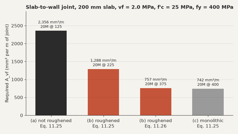
Cl. 11.5 sets no maximum spacing for shear friction bars, but Cl. 21.9.5 limits diaphragm reinforcement to 500 mm each way, so the 375 and 400 mm rows still comply as long as the bars run evenly along the full 5 m. The monolithic row is the one you’d get by treating this joint as one pour, and it asks for 42 percent less steel than the roughened case under Eq. 11.25. Unless both sides really go in one pour, design to a roughened row and leave the monolithic row out of the calc.
Anchor the bars on both sides of the plane
Cl. 11.5.6 requires each bar to develop its yield stress on both sides of the shear plane. If a bar can’t reach \(f_y\), the clamping stress in Eq. 11.27 never develops and the table above doesn’t hold.
On the slab side, a 20M bar usually has the room to run straight. The wall side is the problem: a straight development length for a 20M bar is longer than most wall thicknesses, so the bar needs a standard hook, developed to CSA A23.3-24 Cl. 12.5, inside the wall’s far curtain of steel. To size the embedment and hook for your bar and concrete, check the hooked development length into the wall . For a retrofit, the dowels go into drilled holes in old concrete, and those adhesive anchors are designed to CSA A23.3-24 Annex D, not by hooked development. Their tension capacity often sets the usable \(f_y\).
Check anchorage before you settle the spacing, because a hook that won’t fit in the wall changes the bar size.
Where the procedure changes
- Inclined bars. Cl. 11.5.5 counts only bars sloped so the shear puts them in tension. Those get a \(\sin \alpha_f\) share in \(\sigma\) and a \(\cos \alpha_f\) dowel share with \(\phi_s = 0.85\) (Cl. 8.4.3). Bars that the shear would compress add nothing.
- Permanent compression. \(N/A_g\) adds to \(\sigma\), but Cl. 11.5.4 takes \(N\) as the unfactored permanent load, positive in compression and negative in tension. Gravity on a horizontal joint helps, but live load and seismic axial load don’t count.
- Tilt-up panel bases. Cl. 21.7.3.3 requires shear connectors at the base of every panel and sets \(c = 0\), \(\mu = 0.75\) and \(\phi_c = 0.65\) for the shear friction share. Shear friction can’t carry the base sliding on its own.
For any of these, rewrite \(\sigma\) before solving and keep the same four steps.
Monday checklist
- Walk the lateral load path, find every cast-against-hardened joint on it and confirm the calc uses case (a) or (b), not (c).
- Where you rely on case (b), put the 5 mm roughening note on the drawing at the joint and run Eq. 11.26. It’s often the cheaper answer.
- Draw the dowel’s hook inside the wall before you issue the spacing.