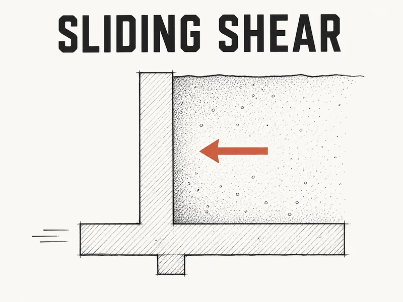
You finish the diagonal shear check on a retaining wall, the stem steel works, and the drawings go out without anyone asking whether the whole wall slides off its footing. Sliding is a stability check, not a strength check, so keep the loads unfactored and hold the factor of safety at 1.5 or more. That’s the friction under the wall’s weight over the horizontal thrust of the soil, \(FS = \mu \Sigma W / H_0\).
That target doesn’t live in CSA A23.3, which is why it gets skipped. The concrete code checks sections, and a wall can have every section right and still move forward as one block. The Canadian Foundation Engineering Manual (CFEM) sets the numbers in its Fig. 20.10. NBC 2020 Article 4.2.4.1 hands the soil side of the check to the geotechnical engineer.
The number people get wrong is the target once a shear key goes in. CFEM asks for 2.0, not 1.5, as soon as passive resistance counts, and on the 3.5 m wall below that turns a 200 mm key into a 600 mm one.
Stability, not strength
Diagonal shear asks whether the concrete can carry a force through a section. Sliding asks something else: whether the stem, the footing and the soil sitting on the heel move together along the base. Nothing in the concrete cracks in that failure, so no amount of stem steel helps. Load and resistance factors build margin into a check you run, and you can see how much those factors add, but they do nothing for a check that never got run.
That’s why the loads stay unfactored. The 1.5 is the whole margin, and it already covers the scatter in both the friction and the earth pressure. Multiply the thrust by 1.5 and then still ask for FS 1.5, and you’ve paid for the same uncertainty twice.
Limit states design is the other route, and it isn’t the softer one. NBC 2020 Sentence 4.1.3.2.(4) puts a factor of 1.5 on earth pressure, and Sentence (5) drops the dead load that resists sliding to 0.9D. On the resistance side, CFEM Table 6.2 gives a typical factor of 0.8 for frictional sliding, anywhere from 0.7 to 0.9 depending on how well the site is known. Put together, friction has to beat the thrust by \(1.5 / (0.9 \times 0.8)\), about 2.1, and passive on a key takes a factor of 0.5. Both routes are defensible, but mixing them isn’t, so ask the geotech which basis their friction coefficient assumes.
There’s one place where sliding is a strength check: the cold joint where the stem sits on the footing. That plane carries factored shear through dowels and concrete friction, and CSA A23.3-24 Cl. 11.5 sizes it with shear friction. Run that one with factored loads and keep it apart from the base check.
The check in four steps
Work on a 1 m strip with unfactored loads.
- Add up what holds the wall down. For a cantilever wall that’s the stem, the footing and the soil on the heel, which CFEM Fig. 20.10 counts as part of the wall. Leave out the surcharge on the heel, since the truck pushing on the wall may not be parked on it, and the soil over the toe, which a future trench can remove. Take off uplift wherever water can get under the base.
- Get the friction coefficient from the geotechnical report. Concrete on clean sand and gravel often gets about 0.5, silts and clays less, and the gap between 0.4 and 0.6 is half again on your resistance.
- Work out the thrust. A free-standing wall can lean enough to drop the pressure to active, but a basement wall held by its floors can’t, so CFEM 20.7.1 puts restrained walls on at-rest pressure. Heavy compaction behind the stem can lock in more, so ask the geotech.
- Compare friction with thrust. \(FS = F / H_0\) needs 1.5. Count passive soil in front of the toe or on a shear key and the target goes to 2.0, using only soil below frost depth, because frost and seasonal swelling weaken anything shallower.
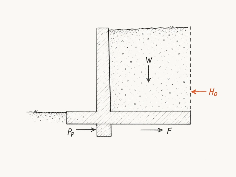
Worked example - a 3.5 m cantilever wall that slides
The wall retains 3.5 m measured to the underside of the footing. A 250 mm stem stands on a footing 400 mm thick and 2.4 m wide, and the 1.55 m heel behind it carries most of the soil that holds the wall down. The backfill is free-draining granular fill over a perforated drain, at 19 \(\text{kN/m}^3\) with a friction angle of 32 degrees, so there’s no water pressure or uplift. A parking lot behind adds 12 kPa of surcharge. The geotech gives a base friction coefficient of 0.50 and 34 degrees for the native soil. The underside of the footing sits at an assumed 0.6 m frost depth, so a key’s passive resistance starts right there.
Sliding check on a 3.5 m cantilever retaining wall
Unfactored loads per 1 m strip, drained backfill (no water pressure or uplift), Rankine active pressure on a vertical plane through the heel, surcharge and toe soil left off
7 input values\(H = 3.5\) m, \(B = 2.4\) m, \(\mu = 0.50\) ...
Step 1: Active pressure coefficient\(K_a = 0.307\)
Step 2: Thrust from the soil\(H_s = 35.7\ \text{kN/m}\)
Step 3: Thrust from the surcharge\(H_q = 12.9\ \text{kN/m}\)
Step 4: Total horizontal thrust\(H_0 = 48.6\ \text{kN/m}\)
Step 5: Weight holding the wall down\(\Sigma W = 132.9\ \text{kN/m}\)
Step 6: Base friction\(F = 66.5\ \text{kN/m}\)
Step 7: Factor of safety as drawn\(FS = 1.37\)
Step 8: Fix 1: heel 200 mm longer\(FS = 0.50 (146.6) / 48.6 = 1.51\)
Step 9: Fix 2: passive coefficient for the key\(K_p = 3.54\)
Step 10: Fix 2: passive on a 600 mm key below frost depth\(P_p = 32.5\ \text{kN/m}\)
Step 11: Fix 2: factor of safety with the key\(FS = 2.04\)
So the wall as drawn slides, at 1.37. The cheap fix is the heel: another 200 mm puts 13.7 kN/m more soil and concrete on the base, and the wall reaches 1.51 on friction alone. A longer heel also shifts where the combined load lands on the footing, so rerun bearing and overturning. A key gets there too, but it has to clear 2.0, and that takes 600 mm below the footing. Hold a 200 mm key to 1.5 instead and it seems to pass, which is exactly the trap.
| Configuration | Resisting (kN/m) | Needed (kN/m) | FS | Target |
|---|---|---|---|---|
| As drawn, B = 2.4 m | 66.5 | 72.9 | 1.37 | 1.5 |
| Heel 200 mm longer | 73.3 | 72.9 | 1.51 | 1.5 |
| 600 mm shear key | 99.0 | 97.2 | 2.04 | 2.0 |
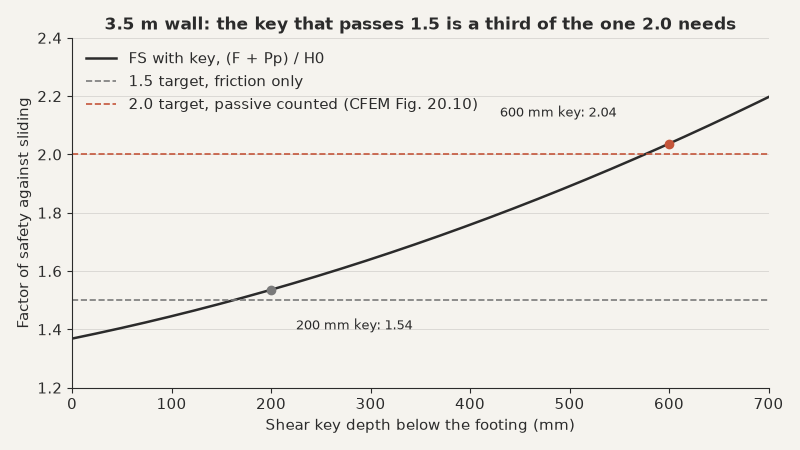
The curve also shows why keys disappoint. The first 200 mm buys about what the longer heel does, but the 2.0 target takes three times that depth. A key also brings two checks of its own. The 2.04 assumes the wall still slips along the footing base, but the slip surface can drop to the key tip and run through soil, which the geotech should check. And the key is a short cantilever off the footing, so it needs flexure, shear and bar anchorage to CSA A23.3 under factored passive load. The 3.54 also assumes the key is cast against undisturbed soil and that the soil in front of the toe stays put, so mark that zone on the drawings as not to be excavated. Widen the heel first, and save the key for the wall where a property line won’t let the heel grow.
Basement walls, water and where the check stops
A basement wall usually gets away with sliding, but not because its footing is better. Its strip footing has no heel, so friction alone would often fail. What saves it is the slab on grade at its base and the floor at its top, which carry the thrust across to the far wall. That only works while the far wall pushes back. A one-sided basement on a slope, a ramp or a big opening leaves the thrust unbalanced, and a sawcut or isolation joint breaks the strut.
Cast tight against the wall, the slab takes the thrust in bearing. Shrinkage or a joint filler opens a gap, though, and then dowels have to tie the two together, developed on both sides the way the shear friction post anchors bars across a slab-to-wall joint.
The weak moment is construction. If the contractor backfills before the slab and main floor are in, the wall stands as a free cantilever on a footing never sized for it. Put the backfill sequence on the drawings, or check that stage as a free-standing wall, with the pressure the geotech gives for a wall that can lean.
The simple check runs out in a few places, and water is the one that breaks it. It adds hydrostatic thrust and lightens the base through uplift, which CFEM Fig. 20.10 takes off W. Seepage under the wall cuts friction and passive resistance too, which CFEM 20.7.3.3 asks the check to cover. Drainage behind the wall is part of the sliding design, not a detail for the spec.
A weak layer under the footing can let the wall slide on that layer instead of at its base, and the check above never sees it. Where frost reaches 1.2 m or deeper, only the part of a key below that depth counts. An earthquake adds the Mononobe-Okabe (M-O) increment, the extra earth thrust from shaking, plus the inertia of the wall and the soil over the heel. On a 4.0 m wall, the seismic retaining wall post shows that inertia running several times the increment.
For a free-standing cantilever wall on drained granular soil, FS 1.5 on friction alone, met with a slightly longer heel, is enough for the static case, and it’s also the cheap answer. It stops holding under seismic load, on clay, wherever groundwater can rise behind the wall, and wherever the geotech hands you factored resistances, because then the check they meant is the limit states one. To see where your own wall lands, run sliding, bearing and the stem steel with your own height, soil friction and surcharge .