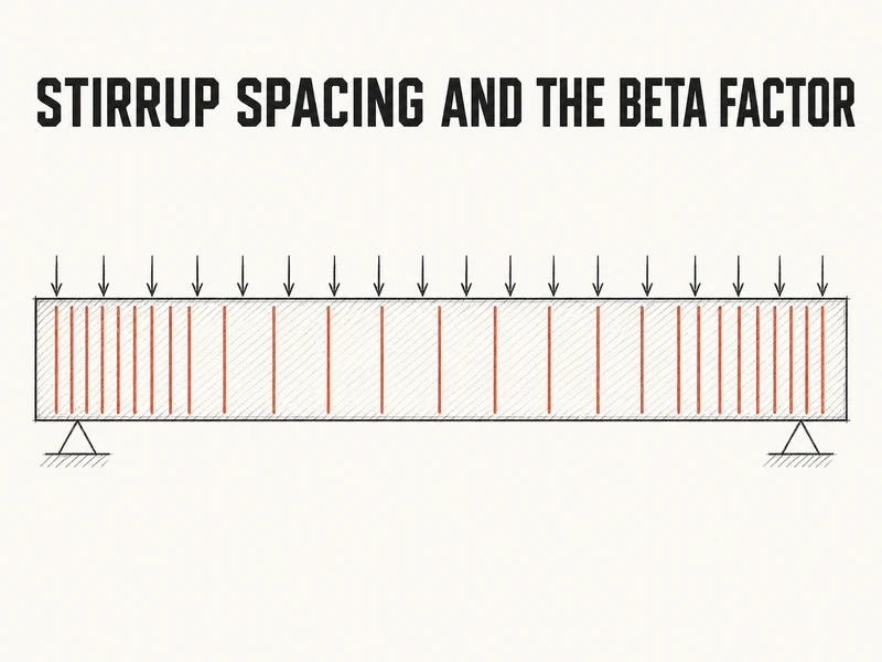
Most stirrup layouts start from the same picture. The stirrups are tight near the supports, wider further in, and there’s a bare stretch in the middle where the concrete carries the shear alone. On a 7.0 m beam 800 mm deep, that bare stretch comes out at 1.64 m long, and the code doesn’t allow it. CSA A23.3-24 Cl. 11.2.8.1 rules it out.
The usual explanation is size. A deep beam without stirrups fails along one long diagonal crack, and the wider that crack opens, the less the aggregate on either face can grip. So past 750 mm, the code stops trusting concrete alone anywhere along the span. A beam deeper than 750 mm gets two stirrup zones instead of three. The same idea sits inside the beta factor, and it’s why the first stirrup you place does more than add steel.
Why beta jumps at the first stirrup
Same beam, same concrete, and the concrete’s share of the shear swings by 30 percent depending on whether a stirrup crosses the crack. That share is \(V_c = \phi_c \lambda \beta \sqrt{f'_c}\, b_w d_v\), where phi_c is the 0.65 concrete resistance factor and lambda is 1.0 for normal-density concrete. Here dv, the effective shear depth, is the larger of 0.9d and 0.72h. Everything else is fixed by the section except beta, the share of shear that the cracked concrete can still pass across the crack. You’d expect beta to be a material constant, like the resistance factor. It isn’t, because it depends on what crosses the crack.
With no stirrups, the simplified method of Cl. 11.3.6.3 takes beta as 230/(1000 + dv), which shrinks as the beam gets deeper, and at dv = 662 mm that’s 0.138. Put in the minimum stirrups and, with bars of 400 MPa or less, beta becomes a flat 0.18 at any depth. The stirrups hold the crack narrow, so the aggregate keeps its grip, the same clamping that lets bars across a cold joint carry shear. That’s a 30 percent jump in Vc before you count any stirrup force at all, which is why the zone of minimum stirrups costs so little.
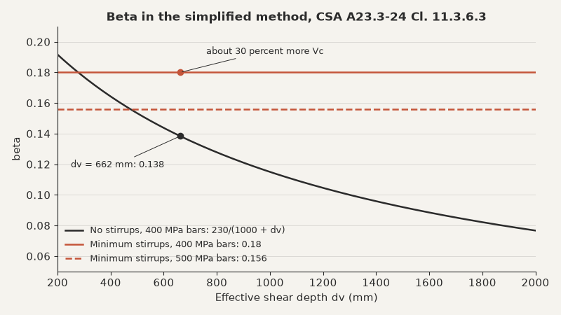
The easy 0.21 you may remember from slabs doesn’t apply to a beam like this. Cl. 11.3.6.2 keeps it, with the crack angle theta at 42 degrees, for shallow members such as slabs up to 350 mm thick and beams no deeper than 250 mm. A beam cast with a slab qualifies too, if it’s no deeper than the lesser of 550 mm and half its web width. So a beam with stirrups and 400 MPa bars uses 0.18 and a 35 degree crack angle at every section, never the depth-penalised value.
The layout in six steps
The order matters, because the first check can end the job before you size a single stirrup.
- Check the ceiling. Cl. 11.3.3 caps the total resistance at \(V_{r,max} = 0.25 \phi_c f'_c b_w d_v\), the force at which the diagonal concrete struts between the cracks crush. More stirrups don’t raise it, so if the shear gets close, the fix is width, depth or concrete strength.
- Find the design shear. Take Vf at dv from the support face, which Cl. 11.3.2 allows when the reaction compresses the beam and no large point load lands inside dv. Then draw the envelope to midspan, where live load on half the span still leaves a shear of factored live load times span over 8.
- Compute Vc with beta = 0.18.
- Set the maximum spacing as the least of 0.7dv, 600 mm and the spacing at which your stirrup still meets the minimum area of Eq. 11.1. Cl. 11.3.8.3 halves the 0.7dv and 600 mm limits, not the Eq. 11.1 spacing, when Vf is over 0.125 times \(\lambda \phi_c f'_c b_w d_v\) or torsion passes a quarter of the cracking torque. The resistance at that spacing is Vr,min, the most the beam carries on minimum stirrups.
- Size the tight zone by solving \(V_s = \phi_s A_v f_{yt} d_v \cot\theta / s\) for s, with Vs taken as Vf minus Vc, then round down to a 50 mm step a crew can tape. Here phi_s is the 0.85 steel resistance factor, Av is the area of all the stirrup legs crossing the crack, and fyt is their yield strength.
- Find the boundaries on the envelope. The tight spacing can stop where Vf falls to Vr,min, and on a beam 750 mm deep or less the stirrups can stop where Vf falls below Vc without stirrups. Deeper than that, they never stop.
Worked example, a 7.0 m beam 500 mm wide and 800 mm deep
Here’s a simply supported beam on a 7.0 m clear span, carrying 150 kN/m factored, of which 60 kN/m is factored live load. It’s 500 mm wide and 800 mm deep in 30 MPa concrete on 400 MPa bars, which puts dv at 662 mm, and the stirrups are two-leg 10M U-bars. The shear is 525 kN at the support face and 52.5 kN at midspan with live load on half the span, so a straight line between them gives 436 kN at dv. You can run the same shear check on your own beam once your envelope is drawn.
Stirrup layout for a 7.0 m beam, 500 x 800 mm (CSA A23.3-24)
Simplified method, theta = 35°, normal-density concrete, vertical stirrups, straight envelope from face shear to pattern-loaded midspan shear
8 input values\(V_{face} = 525\) kN, \(b_w = 500\) mm, \(h = 800\) mm ...
Step 1: Design shear at dv\(V_f = 436\ \text{kN}\)
Step 2: Shear ceiling\(V_{r,max} = 1610\ \text{kN}\)
Step 3: Concrete share with minimum stirrups\(V_c = 212\ \text{kN}\)
Step 4: Maximum spacing\(s_{max} = 463\ \text{mm, use 450 mm}\)
Step 5: Resistance on minimum stirrups\(V_{r,min} = 355\ \text{kN}\)
Step 6: Spacing for the tight zone\(s = 287\ \text{mm, use 250 mm}\)
Step 7: End of the tight zone\(x_1 = 1.26\ \text{m}\)
Step 8: Where a bare zone would start\(x_0 = 2.68\ \text{m}\)
Step 9: Bar tension at the end support\(T = 566\ \text{kN}\)
So the beam gets 10M stirrups at 250 mm out to the 1.26 m boundary at each end. Starting 125 mm from the face, that rounds up to six of them, the last at 1.375 m, and then 450 mm through the middle. The textbook layout would have stopped stirrups at 2.68 m, where the shear falls under the 163 kN the concrete carries alone, and left 1.64 m bare. On an 800 mm beam that’s exactly the stretch Cl. 11.2.8.1 b) fills, and it costs about four stirrups. Shear also pushes about 566 kN into the bottom bars at the support, so anchor them past the bearing.
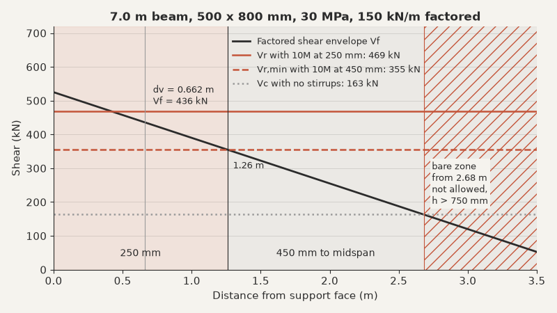
The ceiling never came close, at a ratio of 0.27, which is normal for a gravity beam. Transfer girders and walls under heavy seismic shear are where it starts to govern, and because the only cure is a bigger section, it’s worth running before anything else.
Where the layout changes
Bar grade is the first thing to recheck. A23.3-24 Cl. 11.3.6.3 a) ties beta = 0.18 to longitudinal bars of 400 MPa or less, and for stronger bars it gives 0.4/(1 + fyg/320), which comes to 0.156 at 500 MPa. Rerun the example with 500 MPa bottom bars and Vc drops 13 percent to 184 kN. The 250 mm spacing still passes, but at 0.99, a hair under the limit, instead of 0.93. The tight zone also stretches from 1.26 m to 1.47 m, which takes seven stirrups at 250 mm instead of six. A layout copied from an older job can come up short this way, and it’s the same grade that moves development length for a 500W top bar.
| Case | beta | theta | Clause |
|---|---|---|---|
| Shallow member types | 0.21 | 42 degrees | 11.3.6.2 |
| Minimum stirrups, bars up to 400 MPa | 0.18 | 35 degrees | 11.3.6.3 a) |
| Minimum stirrups, 500 MPa bars | 0.156 | 35 degrees | 11.3.6.3 a) |
| No stirrups, 400 MPa bars, aggregate 20 mm or more | 230/(1000 + dv) | 35 degrees | 11.3.6.3 b) |
Depth is the second. On a beam 750 mm deep or less, the bare middle is legitimate, but it starts where Vf drops below the no-stirrup Vc, the 230/(1000 + dv) value, not the 0.18 one. Using 0.18 there is a common slip, and it’s unconservative, because the bare zone has none of the stirrups that earn the higher number. A wide footing lives in that same no-stirrup case, which is why its one-way shear check lands at a beta of 0.149 instead of 0.21.
The third is a short middle zone. When the stretch at maximum spacing is only two or three stirrups long, running the tight spacing all the way is often simpler on site. A few extra stirrups cost less than a spacing change somebody misses on the rebar sheet.
The simplified method has edges of its own. It covers concrete up to 60 MPa and members without significant axial tension, and the longitudinal bars still need the extra tension that shear puts in them (Cl. 11.3.9). The no-stirrup value of 230/(1000 + dv) also assumes 400 MPa bars and aggregate of at least 20 mm, and with 500 MPa bars it drops to about 203/(1000 + dv). Torsion over a quarter of the cracking torque brings minimum stirrups back too, at any depth. Past those limits, the general method of Cl. 11.3.6.4 sets beta and theta from the strain in the section.
So on any beam deeper than 750 mm, design two zones and let the minimum stirrups run to midspan. That holds while the beam still acts like a beam. Once a significant point load lands within 2d of the support, or the clear span drops to four times d, Cl. 10.7.1 calls it a deep flexural member. The shear stops following a straight envelope there, and the strut-and-tie model of Cl. 11.4 is the tool the code points you to.