The architect has handed you floor plates, and you need to figure out whether a moment frame system will work for seismic resistance. The problem? You don’t have member sizes yet. You don’t know the period. And without the period, you can’t pull loads from the response spectrum. Classic chicken-and-egg.
This post walks through the substitute frame method: a way to convert multi-bay moment frames into simple stick models that give you the global behaviour you need for preliminary design.
Why bother with a substitute frame?
Early in seismic design, you need to answer a few questions: What’s my fundamental period? What kind of drift am I looking at? How much base shear?
The NBCC lets you use an empirical period formula, but it’s conservative. Sometimes very conservative. To refine your design, you’ll want a period from a model. But building a complete frame model with every beam and column when you haven’t sized anything yet? That’s a lot of work for what might be your third iteration.
The substitute frame method is the shortcut. You convert your multi-bay frame into a single-line model (sometimes called a “stick model” or “fishbone model”) that preserves the overall stiffness and mass distribution. Build it in a few minutes, get your period and drift, and move on.
The substitute frame method is for preliminary design, not final member sizing. Use it when you need reasonable global behaviour without getting lost in member-level details.
From multi-bay to single line
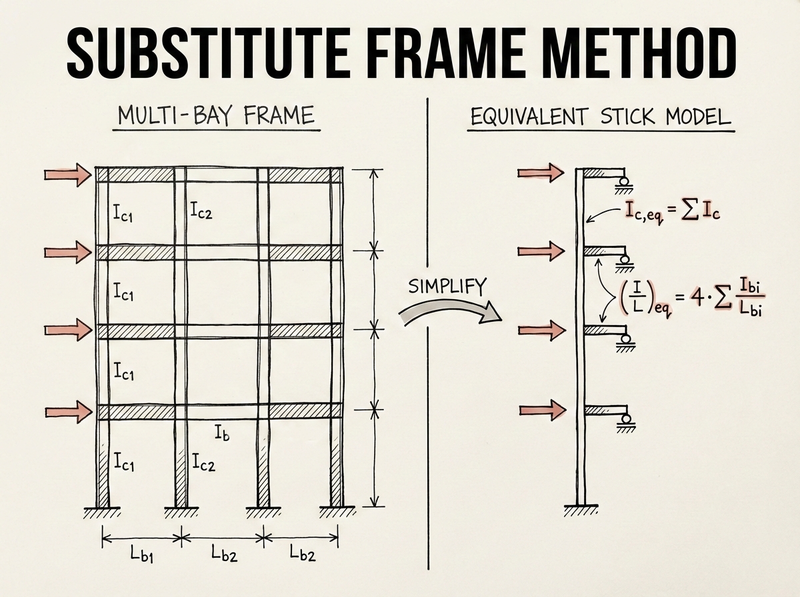
Consider a typical moment frame with multiple bays and stories. You’ve got columns with different sections (\(I_{c1}, I_{c2}, I_{c3}\)…) and beams with different spans and properties (\(I_{b1}/L_{b1}, I_{b2}/L_{b2}\)…).
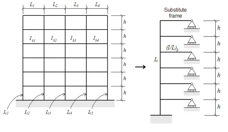
The substitute frame method converts this into:
- A single vertical column element representing all columns at each storey
- A single horizontal beam element at each floor representing all beams at that level
- Pinned supports (rollers) at the beam ends to represent points of inflection
Deriving the equivalent beam stiffness
The assumption here is that under lateral loading, points of inflection occur at the midpoints of the beams. This is reasonable for regular frames. Not exact, but close enough for preliminary work.
Starting from a single joint
Take any interior beam-column joint. When the frame sways, that joint rotates through some angle \(\theta\). The beams on either side resist this rotation based on their stiffness.
For each half-beam (from the joint to the point of inflection at midspan):
- Length = \(L/2\)
- The rotational stiffness contribution depends on \(I/(L/2) = 2I/L\)
Working through equilibrium and compatibility at the joint, accounting for the half-beams on both sides, you end up with:
$$\left(\frac{I}{L}\right)_{eq} = 4 \cdot \sum \left(\frac{I_{bi}}{L_{bi}}\right)$$That factor of 4 comes from two things:
- a factor of 2 from taking half the beam length to the inflection point, and
- another factor of 2 from having beams on both sides of each interior column.
When building your stick model, you can pick any convenient length for your equivalent beam, say 1 meter. Then set \(I\) such that \(I/L\) equals your calculated equivalent value. If \(L = 1\text{m}\), then \(I\) equals your \((I/L)_{eq}\) directly.
Example calculation
Say you have a three-bay frame at a typical floor with:
- Beam 1: \(I = 500 \times 10^6 \text{ mm}^4\), \(L = 6000 \text{ mm}\)
- Beam 2: \(I = 500 \times 10^6 \text{ mm}^4\), \(L = 8000 \text{ mm}\)
- Beam 3: \(I = 400 \times 10^6 \text{ mm}^4\), \(L = 5000 \text{ mm}\)
If you model with \(L = 1000 \text{ mm}\), use \(I = 903{,}333{,}000 \text{ mm}^4 = 903 \times 10^6 \text{ mm}^4\).
Combining column properties
The column side is simpler. Under lateral loading with a rigid diaphragm, all columns at a given storey deflect together. They act as parallel springs, so stiffnesses add directly.
Equivalent column area: \(A_{c,eq} = \sum A_{ci}\)
Equivalent column moment of inertia: \(I_{c,eq} = \sum I_{ci}\)
Just sum them up. No factors needed.
Building the model
Here’s the recipe:
Set up a single vertical line of nodes at storey heights, with one horizontal beam element per floor.
For column elements, use \(I_{c,eq} = \sum I_{ci}\) for bending stiffness and \(A_{c,eq} = \sum A_{ci}\) for axial stiffness.
For beam elements, use any convenient length \(L\), with \(I_b\) calculated so that \(I_b/L = (I/L)_{eq} = 4 \cdot \sum(I_{bi}/L_{bi})\).
Pin (roller) supports go at the far ends of each beam element. These represent the points of inflection where moment is zero.
Apply lateral loads at each floor level on the single column line. Apply floor masses at those nodes for dynamic analysis.
If you’re new to your analysis software, this is a good exercise. You can build a substitute frame model in 15-20 minutes and compare results to a full model later. It builds intuition for how frame stiffness works.
What you get out of this
Run a modal analysis on the substitute frame and you’ll get a fundamental period that’s usually within 10% of a detailed model for regular frames. Apply your lateral loads and you can read off storey drifts, storey shears, overturning moment distribution, and the deflected shape. You’ll see the classic moment frame pattern with largest drift ratios at lower floors, reducing toward the top.
Distributing results back to actual members
Once you have global forces from your stick model, you can distribute them back to individual members:
- Beam moments distribute in proportion to their \(I/L\) values
- Column shears and moments distribute in proportion to their \(I\) values (or \(I/L\) for different storey heights)
This gets you in the ballpark for preliminary sizing. You’ll still need a detailed model for final design, but you’ll start that model with much better initial guesses.
Limitations
The substitute frame method works well for regular frames with reasonably uniform bay widths and storey heights, and for symmetric buildings without torsional irregularity.
It falls short when you have setbacks, soft stories, or non-uniform bays. It also won’t give you accurate enough results for final design and code checking. If the building is torsionally sensitive, the load distribution depends on actual stiffness distribution in plan, which a single stick can’t capture. Same goes for flexible diaphragms.
For irregular buildings or final design, you’ll need the complete frame model. But even then, the substitute frame gives you a sanity check. If your detailed model’s period is way off from your simple model, something might be wrong.
Practical tips
Build the substitute model first. Use it to understand global behaviour. Then build the detailed model with the preliminary sizes your simple model helped you pick.
If you do a lot of mid-rise concrete or steel moment frame buildings, keep templates of substitute frame models. Swap in the properties for each new project and you’ll save yourself setup time.
Watch out for shear deformation if you’re working with squat members or deep coupling beams. Most frame analysis software can include this if you specify the shear area. For tall, slender frames, it’s less of a concern.
The first few times you use this method, build both the simple and detailed models. Compare periods, drifts, and force distributions. You’ll quickly develop a feel for when the simple model is “close enough” and when you need more detail.
Going further
Pick a recent project with a moment frame and build the substitute frame model. Compare results to your detailed analysis. If you work with dual systems, try combining substitute frames with stick models for braced frames or walls. And if you want to understand where the method breaks down, dig into the derivation. The factor of 4 comes from specific assumptions about inflection points, and knowing those assumptions tells you when to be skeptical of the results.