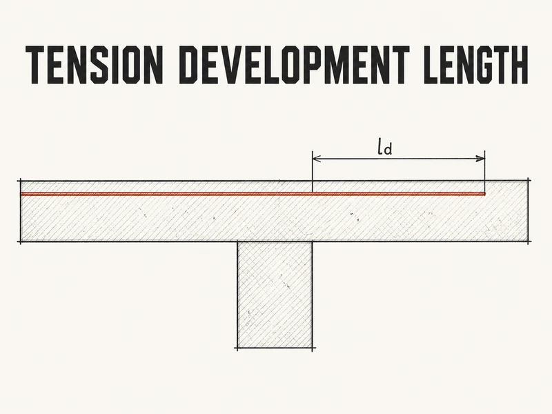
Swapping 400W bars for 500W to save steel feels like a 25 % hit on development length, since the yield strength went up by 25 %. Under CSA A23.3-24 it’s closer to 39 %, because the 2024 edition added a fifth modification factor that grows with the bar grade. A 25M top bar in 30 MPa concrete goes from 1077 mm to 1501 mm, and that can push a cut-off or a lap splice past where the drawings put it. CSA A23.3-24 Cl. 12.2.3 and Table 12.2 set the length.
Five factors, and the two that usually move
Before any factor, the simplified equation makes you pick a multiplier, and that choice moves the answer more than most factors do. You take 0.45 when the member has minimum stirrups or ties along the whole length, or when the bars have two diameters of clear space between them and one and a half of cover. Anything else takes 0.6, which is a third longer. So a bar that comes out too long is worth checking for stirrups before you hunt through the factors, which scale the length for conditions that weaken or help bond. If you learned them as K1 to K4, the 2024 edition renamed them and added one more.
| A23.3-19 | A23.3-24 | What it covers | Usual value |
|---|---|---|---|
| \(k_1\) | \(k_\ell\) | Bar location | 1.3 for top bars, else 1.0 |
| \(k_2\) | \(k_c\) | Coating | 1.0 uncoated; 1.2 or 1.5 epoxy; 1.2 galvanized |
| \(k_3\) | \(k_d\) | Concrete density | 1.0 normal; 1.2 semi-low; 1.3 low-density |
| \(k_4\) | \(k_s\) | Bar size | 0.8 for 20M and smaller; 1.0 for 25M and up |
| none | \(k_g\) | Reinforcement grade | 1.0 up to 400 MPa; 1.12 at 500 MPa |
In most Canadian buildings the bars are uncoated and the concrete is normal density, which leaves bar location and bar size doing the real work. Bar location is the one with the surprising definition, because “top bar” is set by how much fresh concrete was placed under it, not by where the steel sits in the member. Once more than 300 mm of concrete sits below a horizontal bar, bleed water and trapped air rise and collect on its underside. So the bar ends up bonded to a weak, porous layer instead of sound paste.
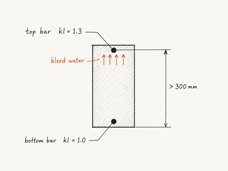
That’s why the negative steel over a support in a 600 mm beam takes 1.3 while the bottom steel takes 1.0. The top mat in a 200 mm slab stays at 1.0, except where it runs over a deeper beam cast with it. Bar size goes the other way. A 20M or smaller bar has more surface for the force it carries, so it gets a 20 % reduction, and that 0.8 is one of the few factors that hands you length back.
Worked example - what 500W does to a top bar
Take four uncoated 25M top bars over an interior support of a 600 mm beam in 30 MPa normal-density concrete. The beam has minimum stirrups throughout, so the 0.45 multiplier applies, and the bars are top bars. The cut-off on the drawings sits 1200 mm past the section where the bars need their full yield stress. Switch the spec to 500W and a new factor joins in. The grade factor is \(k_g = f_{yg}/900 + 0.56\) for bars above 400 MPa, which works out to 1.12 at 500 MPa (1.1156 before rounding). The catch is that it multiplies the yield strength term, which already went up by 25 %, so the two stack to about 1.39. Bond gets less efficient as bar stress climbs, so 25 % more force needs more than 25 % more length.
25M top bars over an interior support, 400W against 500W
Simplified equation; 400 mm web, 40 mm clear cover, 10M stirrups throughout; uncoated bars, normal-density concrete
6 input values\(f'_c = 30\) MPa, \(d_b = 25.2\) mm, \(L_{avail} = 1200\) mm ...
Step 1: Development length with 400W bars\(\ell_d = 1077\ \text{mm}\)
Step 2: Grade factor for 500W bars\(k_g = 1.1156\)
Step 3: Development length with 500W bars\(\ell_d = 1501\ \text{mm}\)
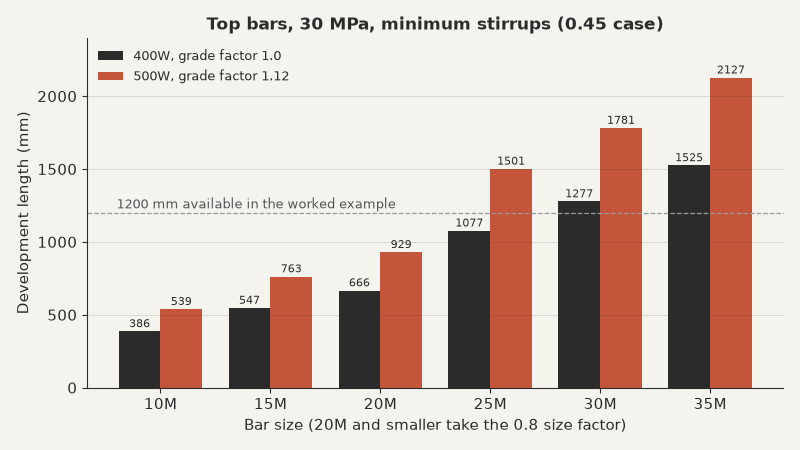
So the 400W detail clears with about 120 mm to spare, while the same bars in 500W fall 300 mm short. You’d either extend the cut-off or drop to 20M bars, which pick up the 0.8 size factor and need only 929 mm in 500W. It takes seven to match the steel area, and seven won’t fit in one layer of this web at the spacing the equation needs. That’s the development check only, so the Cl. 11.3.9 shear extension and the Cl. 12.10 and 12.12 cut-off rules still apply. If extending isn’t possible at an exterior support, a hook is usually the next move, and the hooked bar post walks through the factors that shrink a 25M hook into a 600 mm column.
Where the simplified equation stops
The simplified equation only applies when clear cover is at least one bar diameter and clear spacing at least 1.4 diameters. The product of the location and coating factors is capped at 1.7, which only bites on top bars that take the 1.5 coating factor. No development length goes below 300 mm either, which is why a 10M bottom bar in 400W steel at 30 MPa, with the 0.45 multiplier, computes to 297 mm and still gets 300.
The excess reinforcement reduction in Cl. 12.2.5 is tempting, but it’s off the table where development of full yield is specifically required. That covers shear friction dowels, which have to develop yield on both sides of the plane, and seismic detailing under Clause 21.
The 2024 edition also reworded the spacing route to 0.45. A23.3-19 limited it to slabs, walls, shells and folded plates, while A23.3-24 opens it to any member that meets the spacing and adds a clear cover limit of 1.5 bar diameters. The catch is slabs. A 15M bar with 20 mm of cover falls under the new 24 mm limit, so without ties it drops to 0.6, and an old slab table at 0.45 comes out a quarter short.
For 400W bars in a normal building, the top bar and small bar factors still carry most of the change, as long as you recheck which multiplier the cover allows. The shortcut stops holding the moment the specification says 500W or galvanized, because each of those adds a factor that a table built on K1 to K4 never carried. That’s the point to recompute rather than look up, the same way an equation you use without seeing its assumptions turns into a design error.