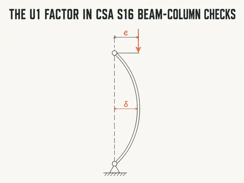
A 6.0 m W250x67 carries 1500 kN and 80 kNm. Run the overall member check with the moment factor at 1.0, because that looks safe, and the column fails at 1.06. Use the value S16 actually gives for a pinned base and the same column passes at 0.93.
That factor sits inside U1, the part of the beam-column equation that accounts for the column bowing out between its ends. CSA S16-19 Cl. 13.8.5 defines U1, and it multiplies the moment about each axis, here the strong axis. At this column’s load the amplifier alone would raise the moment term by about a third, and the moment gradient factor can then pull it back below 1.0:
$$U_1 = \frac{\omega_1}{1 - C_f/C_e}$$Here \(C_e\) is the Euler load, the elastic buckling load in the plane of bending, \(\pi^2 EI/L^2\). The \(1/(1 - C_f/C_e)\) part is the amplifier, and \(\omega_1\) is the moment gradient factor that most of the trouble comes from.
The moment gradient factor and the sign of kappa
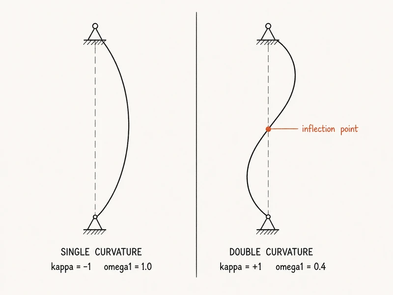
The amplifier on its own assumes the worst shape, one smooth curve with the biggest bow right where the moment is biggest. With a moment at the top and a pinned base, the moment tapers to zero, so the bow at mid-height acts on only half the end moment. Bend the column into an S and the two halves bow in opposite directions and mostly cancel. So \(\omega_1\) swaps the real moment diagram for an equivalent uniform one, which is why it can sit well below 1.0.
For a member with end moments only, Cl. 13.8.6 sets it at 0.6 minus 0.4 times \(\kappa\), the ratio of the smaller end moment to the larger, and never less than 0.4. This is where people trip. You’d expect single curvature to be the positive case, since the moments seem to agree, but S16 makes \(\kappa\) positive for double curvature and negative for single. Equal moments in one smooth curve give -1 and a factor of 1.0, and equal moments in an S give +1 and the 0.4 floor.
Loads between the ends change the rule: 1.0 for a distributed load or a row of point loads, and 0.85 for a single concentrated load or moment. A crane bracket partway up is that second case, because its reaction times its offset is a moment applied between the supports. Folding it into one equivalent eccentricity at the column top would move that moment to the ends, which is a different column from the one you have.
Worked example - the 6.0 m W250x67 with a girder moment
This is the braced-frame column that needed an Annex G value of K to carry 2150 kN of balanced gravity load, with the girder moments cancelling. That only holds with no moment at all, since check (b) goes back to K = 1 and 2050 kN. Here, pattern live load empties one girder, dropping the axial load to 1500 kN but leaving 80 kNm at the top. The pinned base takes no moment, so \(\kappa\) is 0. The weak-axis struts still restrain twist every 2.0 m, so lateral-torsional buckling stays simple.
U1 and the three Cl. 13.8.2 checks for a 6.0 m W250x67 in a braced frame
Braced frame, strong-axis bending only, pinned base, 345 MPa steel; Class 1 (flange b/t 6.5 against 7.8, web h/w 25.4 against 46); weak axis and twist braced at 2.0 m
8 input values\(C_f = 1500\) kN, \(M_{fx} = 80\) kNm, \(L = 6000\) mm ...
Step 1: Euler load about the bending axis\(C_e = 5700\ \text{kN}\)
Step 2: Amplifier\(1.36\)
Step 3: Moment gradient factor\(\omega_1 = 0.6\)
Step 4: U1 for the strong axis\(U_{1x} = 0.814\)
Step 5: Moment resistance\(M_{rx} = 280\ \text{kNm}\)
Step 6: Axial resistance for each check\(C_r = 2655,\ 2050,\ 2360\ \text{kN}\)
Check (b) governs at 0.93, and it’s the only one of the three where a U1 under 1.0 counts. Default \(\omega_1\) to 1.0 and the same check reads 1.06, so you’d upsize a column that passes this case. Checks (a) and (c) rise too, to 0.90 and 0.97, but the 1.0 floor stops them dropping below 0.81 and 0.88.
Check (b) only moved because of how the amplifier is built. Put an axial load on a column that’s already bending and the load doesn’t stay where you drew it. The end moments bow the column sideways, so at mid-height the load acts a little off the centroid, and that offset times the load is extra moment your first-order analysis never saw. That is the P-delta effect, and more moment means more bow, which means more moment again. Below the buckling load the loop settles at a bigger number, but at the Euler load it never settles at all. Without it, the check would be plain P/A plus M/S, which is where the interaction equation starts.
Bend a pin-ended column into one smooth curve with equal end moments and the loop has an exact elastic answer, the end moment times a secant. The angle inside that secant grows with the square root of the load ratio. Nobody wants a secant on every column, so S16 uses \(1/(1 - C_f/C_e)\) instead, which has the same asymptote and tracks it well at low load ratios. It runs low, on the unconservative side, by about 2 percent at a load ratio of 0.1 and 6 percent at this column’s 0.26.
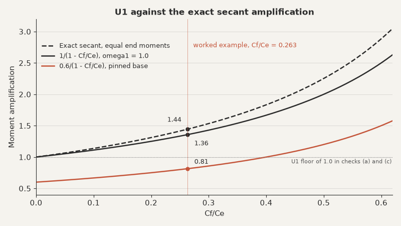
That 6 percent is small next to the 40 percent the moment gradient factor took off this column’s equivalent uniform moment in check (b).
Where U1 stops working for you
The 1.0 floor is the first limit. For a strong-axis moment, Cl. 13.8.2 lets U1 fall below 1.0 only in the overall member check, because there it stands for an equivalent uniform moment along the whole member. The cross-section check and the lateral-torsional buckling check keep it at 1.0 or more.
The second limit is the frame. In an unbraced frame, checks (b) and (c) simply take U1 as 1.0, and the frame-level P-Delta, usually the bigger effect there, is picked up in the Cl. 8.4 analysis instead. So U1 earns its keep in braced frames.
Then there’s the Euler load itself. It uses the full member length and the I about the bending axis, so a strong-axis moment needs the strong-axis I even when the weak axis governs buckling. Put the weak axis in by habit and this column’s Euler load drops to about 1200 kN, below the load it carries, so the formula breaks.
So refine the moment gradient factor whenever the overall member check is the one that fails, because here it cut the moment term from 0.33 to 0.20 just for reading the moment diagram. It buys less once the cross-section or lateral-torsional buckling check governs, because the floor stops U1 falling there. The end-moment formula also stops applying once a load lands between the ends, where 1.0 or 0.85 takes over. Then check your own column with its real moment diagram .