You’ve set up your structural model, defined your sections, and then the software asks for “shear area.” What do you put there? Most of us have typed in zero and moved on. But do you know what that actually does to your analysis?
What that shear area field does
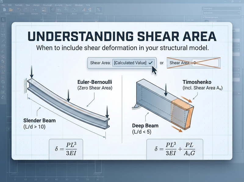
When you enter a shear area value, you’re telling the program whether to include shear deformation in the stiffness calculations. Most engineers don’t realize this:
Entering zero doesn’t mean “zero shear capacity.” It means “ignore shear deformation entirely.”
Most commercial programs treat a zero as an instruction to use classical Euler-Bernoulli beam theory, which assumes plane sections remain plane and perpendicular to the neutral axis. That works fine for slender beams where bending deformation dominates. For deeper sections or shorter spans, though, shear deformation adds meaningfully to your total deflection.
A zero in the shear area field won’t break your model. It just tells the software to skip the shear flexibility contribution. For most typical beams, that’s perfectly acceptable.
Why shear area isn’t just “area”
The shear area you need to enter isn’t the same as your cross-sectional area. Shear stress doesn’t distribute uniformly across a section. It varies parabolically for rectangular sections, peaking at the neutral axis and dropping to zero at the extreme fibres.
The “shear area” (often written as \(A_v\) or \(A_s\)) is an effective area that accounts for this non-uniform distribution.
For rectangular sections:
$$A_v = \frac{5}{6} \times b \times d = \frac{bd}{1.2}$$That 5/6 factor (or dividing by 1.2) comes from integrating the actual shear stress distribution and finding the equivalent uniform stress that produces the same strain energy.
For I-shaped sections:
$$A_v \approx A_{web} = d \times t_w$$The web carries almost all the shear in a wide-flange section, so the web area is a reasonable approximation. Some references use more refined factors, but web area gets you in the right ballpark.
For other sections, the shear area factor varies by geometry. Solid circular sections use about \(A/1.11\). Thin-walled tubes get more involved. Check your steel design manual for the specific form factor for your section type.
If you’re using standard steel sections from a library, the software may already have the shear area calculated. Check your section properties to see if \(A_v\) is populated. You might not need to enter anything manually.
When shear deformation actually matters
The total deflection of a beam has two components:
- Flexural deflection (from bending), proportional to \(PL^3/EI\)
- Shear deflection (from sliding), proportional to \(PL/(A_v G)\)
For a tip-loaded cantilever, the deflection formula including both effects is:
$$\delta_{total} = \frac{PL^3}{3EI} + \frac{PL}{A_v G}$$The ratio of shear deflection to bending deflection scales roughly with \((\frac{d}{L})^2\). In practice:
- At span-to-depth ratios above 10, shear deformation is typically a few percent of total deflection. You can ignore it.
- Between 5 and 10, shear effects become noticeable, maybe 5-15% of total deflection.
- Below 5, you’re in deep beam territory. Shear deformation can reach 20-30% or more of your total deflection. Ignoring it will underestimate your deflections.
I see this come up most often when engineers model plate girders, spandrel beams, or transfer beams as standard beam elements without including shear area. These members tend to have low span-to-depth ratios where shear flexibility matters.
The stiffness matrix connection
If you want to see what’s happening mathematically, the beam stiffness matrix changes when you include shear deformation. The modified matrix includes a factor Γ:
$$\Gamma = \frac{12EI}{A_v G L^2}$$When \(\Gamma = 0\) (infinite shear area), you get the standard Euler-Bernoulli stiffness matrix. As \(\Gamma\) increases, the beam gets more flexible. The stiffness terms get multiplied by \(1/(1+\Gamma)\), which is always less than 1.
In practice, this means including shear deformation makes your structure more flexible, which leads to larger deflections and can change load distributions in indeterminate structures.
When to include it and when to skip it
You can probably ignore shear area (enter zero) for:
- Standard floor beams and joists (\(L/d > 12\) typically)
- Roof beams and purlins
- Most moment frame members
- Situations where deflections aren’t critical and you’re comfortable with slightly conservative stiffness
You should include shear area for:
- Plate girders and deep transfer beams
- Stub cantilevers (corbels, short bracket arms)
- Spandrel beams with low \(L/d\) ratios
- Members where you need accurate deflection predictions
- Deep beam-column joints modeled with rigid links
- Seismic analysis where stiffness distribution affects the results (including simplified stick models for preliminary design)
If you’re learning the software, try running the same model with and without shear area for a simple cantilever. Compare the deflections. You’ll quickly build intuition for when it matters.
Software-specific notes
Most commercial programs handle this the same way:
- SAP2000 / ETABS: Zero shear area means shear deformation is excluded. Section properties from the built-in database often include \(A_v\) values.
- S-Frame: Includes shear deformation when shear area is specified. Check their documentation for the exact formulation.
- RISA: Same behaviour. Zero excludes shear effects.
If your program doesn’t explicitly ask for shear area, check whether it’s using Timoshenko beam theory (includes shear) or Euler-Bernoulli (excludes shear) by default.
A quick validation check
Not sure if shear deformation matters for your situation? Run these numbers:
- Calculate the flexural deflection by hand: \(\delta_{flex} = PL^3/(3EI)\) for a cantilever, or the appropriate formula for your configuration
- Estimate the shear deflection: \(\delta_{shear} = PL/(A_v G)\)
- If \(\delta_{shear} / \delta_{flex} < 5\%\), you’re fine ignoring shear effects
- If it’s approaching 10-15% or more, include the shear area in your model
For rectangular sections with typical steel properties (\(E/G \approx 2.6\)), this ratio works out to roughly:
$$\frac{\delta_{shear}}{\delta_{flex}} \approx 2.6 \times \left(\frac{d}{L}\right)^2$$Plug in your depth and span and you’ll have your answer in about 30 seconds.
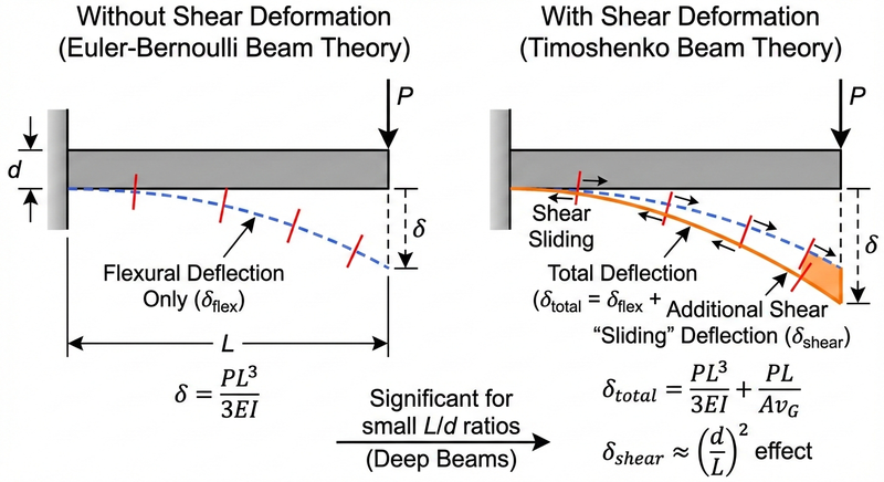
Comparison of deflected shapes for a cantilever beam with and without shear deformation, showing the additional “sliding” displacement from shear
Back to that field in your model
So what do you do when the shear area field pops up?
For most routine work, enter zero and move on. That’s standard practice for typical beam elements where \(L/d\) is large. For deep members, calculate \(A_v\) using the appropriate form factor. Rectangles get \((5/6)bd\). I-shapes, use the web area. And when you need accurate deflections, whether you’re checking serviceability on a transfer beam or validating against test results, include it.
The point isn’t to always include shear area or always ignore it. It’s to know what the software does with that input so you can make the call deliberately. ./