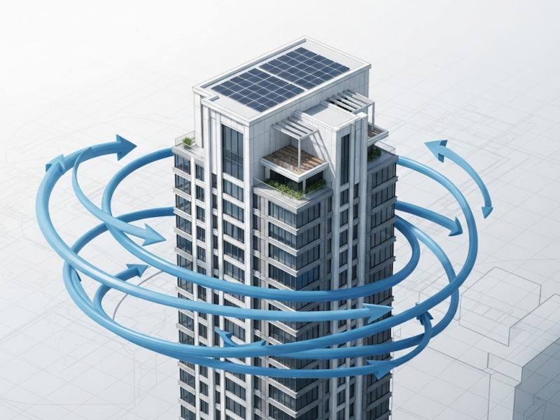
Another code cycle, another round of changes to get our heads around. Just when you think you’ve got your spreadsheets perfected, the new National Building Code of Canada (NBCC) lands on your desk. While the 2020 edition brought updates across the board, the wind load provisions in Subsection 4.1.7. have some particularly noteworthy changes that are already impacting our designs.
Wind design can be tricky. It’s a mix of statistics, aerodynamics, and structural dynamics that can feel a world away from our day-to-day concrete and steel design. The code committee has been busy, and four key areas have seen significant updates:
- Attached Canopies: New specific provisions for a common architectural feature.
- Parapets: More detailed guidance on pressures for these often-underestimated elements.
- Roof-Mounted Solar Panels: Finally, code-based rules for the ever-popular green energy addition.
- Partial Wind Loading: A revision to how we handle torsional and combined load effects.
What follows walks through what’s new, what it means for your projects, and how to apply it without pulling your hair out.
1. Attached Canopies
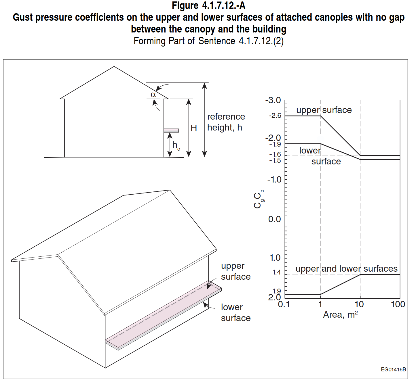
For years, designing canopies attached to buildings felt like a bit of a no-man’s-land in the code. We’d often have to extrapolate from other provisions or rely on engineering judgment. The NBC 2020 brings much-needed clarity with Article 4.1.7.12. for low buildings (H ≤ 20 m) and supplementary guidance in the Commentary for taller structures.
The key is understanding that you’re essentially doing two design checks: one for the cladding and another for the canopy structure itself.
- For Cladding/Components: You need to find the pressures on the separate upper and lower surfaces. This is for designing the soffit, the top membrane, and their fasteners. For low buildings, you’ll use Figure 4.1.7.12.-A. The commentary provides Figure I-7 for buildings taller than 20 m.
- For the Canopy Structure: For the main structural elements (joists, beams, columns, and the connection to the building), you’ll use the net pressure coefficients. These account for the simultaneous action of wind on both surfaces. Use Figure 4.1.7.12.-B for low buildings and Figure I-8 from the commentary for taller ones.
 Source: NBCC 2020
Design reminder: Don’t mix them up. Use the separate surface pressures for your cladding design and the net pressures for your structural design. It’s a simple distinction that prevents over- or under-designing your canopy components.
2. Parapets
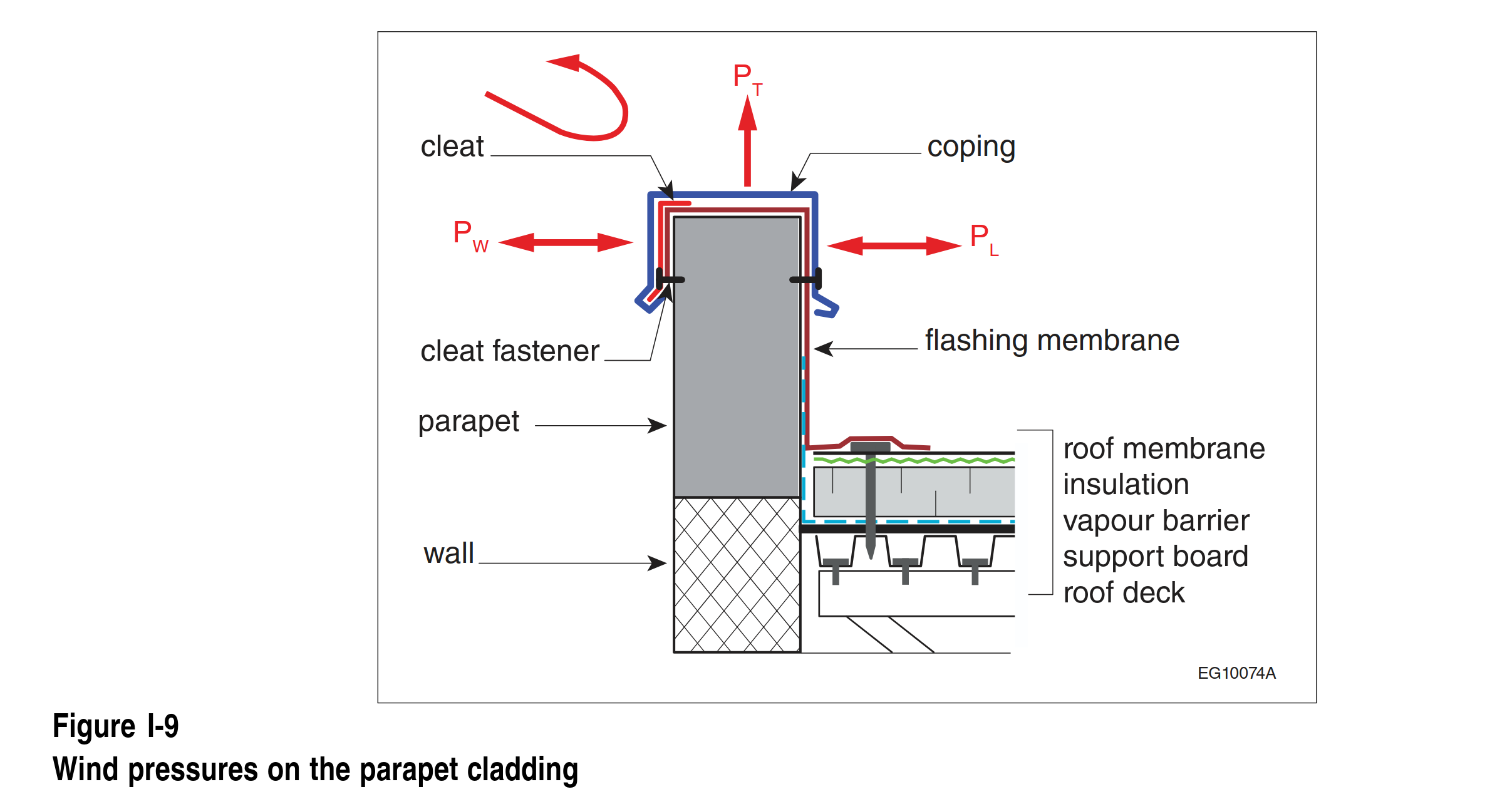
We’ve all seen coping get peeled off a roof in a windstorm. Parapets create complex aerodynamic effects at roof edges, and the NBC 2020 gives us a more refined way to handle these high-pressure zones.
The core of the guidance is in Clause 4.1.7.5.(9) for cladding on parapets. The commentary clarifies that we need to consider three distinct pressures (see Figure I-9):
- PT: Uplift on the top (coping).
- PW: Pressure on the windward-facing side.
- PL: Suction on the leeward (inner) side.
 Source: NBCC Commentary
The pressure coefficients for these surfaces are tied to the zones on the building they are adjacent to. \(P_W\) is determined using the coefficients for the wall below, while \(P_T\) and \(P_L\) use the roof edge or corner coefficients.
Watch for: According to Sentence 4.1.7.7.(2), when you’re designing the parapet cladding itself, you must use an internal pressure coefficient (Cpi) of ±0.70, regardless of the building’s opening category. This accounts for the potential for the parapet structure to be pressurized from below, creating some pretty significant net pressures on the cladding. Don’t miss this.
3. Roof-Mounted Solar Panels
With the push for sustainable design, solar panels are popping up on roofs everywhere. Previously, we had to rely on manufacturer data or specialized wind tunnel testing. Now, Article 4.1.7.13. gives us a codified method for most common installations. This complements the code’s approach to handling snow loads on solar panels.
The approach depends on the panel’s geometry and orientation.
For Panels Parallel and Close to the Roof
If panels are installed close to the roof (≤ 250 mm high), the code recognizes that pressure equalization can occur between the top and bottom surfaces, reducing the net load. The design pressure is calculated using a pressure equalization factor, γa, found in Figure 4.1.7.13.-A. However, this reduction doesn’t apply near the edges of the solar array, where you’ll need to use an edge factor, E = 1.5.
For Tilted Panels (or Panels Far from the Roof)
This is the more common scenario. For tilted panels on low-slope roofs (≤ 7°), you calculate a net pressure using a new formula for the net gust pressure coefficient, (Cg Cp)net. This formula pulls together several new factors:
| Factor | Description |
|---|---|
| γp (Parapet Factor) | Accounts for the increased wind loads on solar panels that can be caused by the presence of a roof parapet. |
| γc (Chord Factor) | Adjusts the wind load based on the chord length (size) of the solar panel. |
| E (Edge Factor) | Applies a higher load multiplier to panels located at the exposed edges of a solar array where wind pressures are typically greater. |
| (CgCp)n (Normalized Gust Pressure Coefficient) | This is the base pressure coefficient that accounts for the panel’s tilt angle (ω) and normalized area (AN) before other adjustments are applied. |
Here is a summary of the key factors used in the National Building Code of Canada 2020 for calculating wind loads on tilted solar panels.
The commentary provides a great sample calculation (Paragraph 76) that walks through this process step-by-step. It’s worth running through it. The big takeaway is that the loads on the panels can, in some cases, be more critical than the loads on the bare roof, potentially requiring you to strengthen the underlying roof structure.
4. Revised Partial Wind Loading: Capturing Torsion
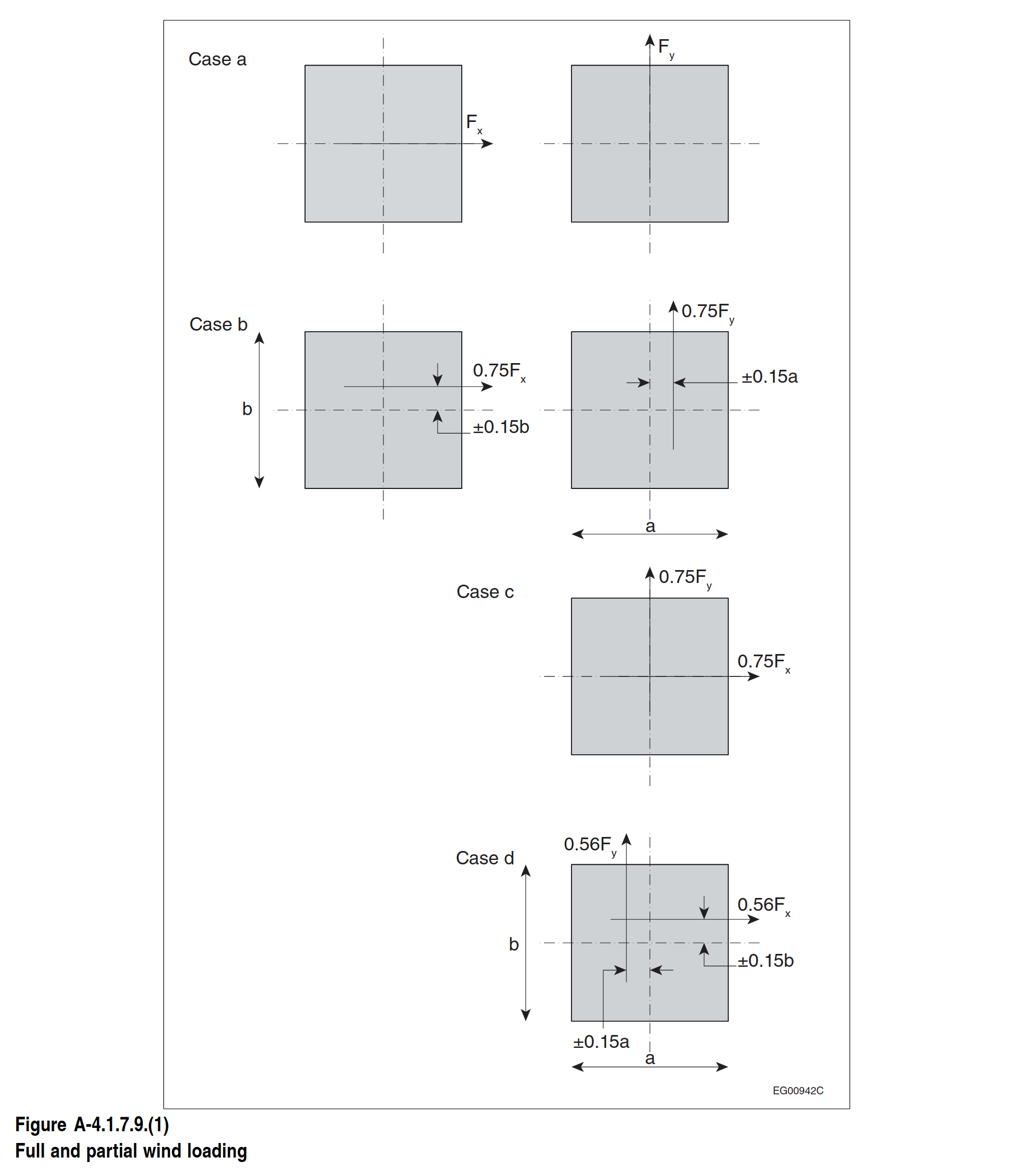
Finally, the provisions for partial loading have been updated in Sentence 4.1.7.9.(1) to better capture torsional effects and loads from diagonal wind directions. This applies to buildings designed with the Static or Dynamic procedure, but not those using the simplified Cg Cp values from Article 4.1.7.6.
Instead of just one case for eccentricity, we now have four primary load cases to check:
- Case a: 100% of the wind load along each principal axis, separately. (The standard case).
- Case b: 75% of the wind load, offset by 15% of the building width to create torsion.
- Case c: 75% of the wind loads on both principal axes applied simultaneously (to simulate a cornering wind).
- Case d: 56% (75% of 75%) of the wind loads on both axes, with torsion on both.
 Source: NBCC 2020
While these load combinations might seem like more work, they provide a more realistic picture of how buildings respond to turbulent, shifting winds. For many symmetrical buildings, Case (a) will still govern. But for buildings with irregular shapes or lateral systems sensitive to torsion, these new cases could easily become the critical design drivers.
The Bottom Line
The wind load updates in the NBC 2020 are a clear step toward providing more rational, data-driven procedures for common design challenges. We now have explicit tools to tackle canopies, parapets, and solar panels, and a more thorough approach to partial loading for taller or more complex buildings.
Getting familiar with these changes now will save you headaches on your next project. It means updating your templates, but it also means building safer, more resilient structures based on the latest research.
As you fold these 2020 updates into your workflow, it’s worth revisiting any “standard” wind details or spreadsheets that were calibrated to earlier editions so they keep pace with how NBCC now expects us to handle these elements.