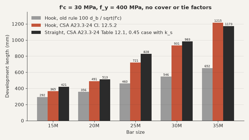
Under the old rule, a 25M hook needed about 460 mm. That’s the number most people still carry around. CSA A23.3-24 changed the equation, and the same bare hook in 30 MPa concrete now needs 721 mm. Cl. 12.5.2 sets the new length. That can push a hook out the back of an exterior column.
The good news is that cover and ties win most of it back. Get both and that 25M hook drops to 346 mm.
What changed in the 2024 hook equation
You’d expect a code update to nudge a number by ten percent. This one changed the shape of the equation. A23.3-14 used \(100 d_b / \sqrt{f'_c}\) for 400 MPa bars. The 2024 equation looks like this:
$$\ell_{dh} = \frac{k_\ell k_c k_d k_r f_{yg} d_b^{1.5}}{30 {f'_c}^{0.25}}$$Here \(d_b\) is the bar diameter and \(f_{yg}\) its grade yield strength. The k terms are modification factors, and a bare hook has them all at 1.0. Bar diameter now enters to the power 1.5, so big bars get hit hardest. Concrete strength enters to the power 0.25, so stronger concrete helps less than it used to.
You’d think a hook is always the short option. At 30 MPa, a bare 35M hook needs 1215 mm. A straight 35M bottom bar with minimum stirrups needs only 1173 mm. So until you earn the factors below, a 35M hook saves nothing, and an old table can’t be patched.
Where the length comes back: cover and ties
Table 12.5 has two factors that reward good detailing, and they multiply.
| Factor | Value | When it applies |
|---|---|---|
| Cover | 0.8 | 35M and smaller with side cover, normal to the hook plane, of at least 6 bar diameters, or a hook ending in a column core with at least 60 mm |
| Ties | 0.6 | 35M and smaller, ties whose legs total at least 40 % of the hooked bar area, or hooked bars spaced at least 6 bar diameters |
On the tie route, the code needs two or more ties enclosing the hook, no more than 8 bar diameters apart. Parallel ties must also sit within 10 bar diameters of the bar. Together they cut the hook to 48 % of its basic length, so detail the ties first, then size the hook.
Worked example: a beam hooked into a 600 mm exterior column
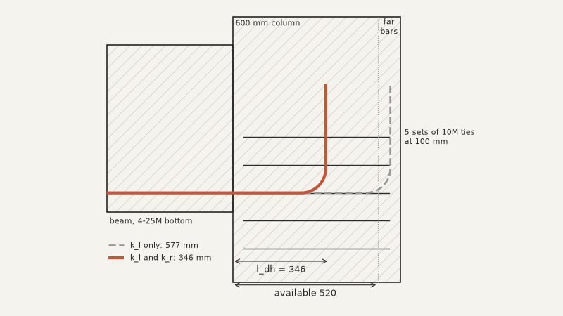
Four uncoated 25M bottom bars end in a 600 mm deep column at an intermediate floor. The beam is also 600 mm deep, in 30 MPa concrete. The hook has to stop inside the far column bars, which leaves about 520 mm. The beam is part of a conventional construction frame in the lateral system, so Cl. 12.11.2 wants these bottom bars developed for full yield in tension at the column face. A straight 25M with minimum stirrups would need 828 mm, so it has to hook.
The column is 550 mm wide and the beam 400 mm, so the outer hooks sit about 125 mm in from the column face. That clears the column’s 25M corner bars and leaves plenty of side cover in the core, which earns the cover factor. The column also carries on above, which keeps the top cover clear of the Cl. 12.5.6 limit. But the bars sit about 90 mm apart, under 6 bar diameters, so the tie factor has to come from ties. Five sets of two-leg 10M column ties at 100 mm give 1000 square millimetres of legs, centred on the bars, with two sets below the soffit. That’s 50 % of the hooked bars, and four sets would exactly meet the 40 %. Those ties still have to meet the column and joint tie rules; here they’re only counted for anchorage. Joint shear and the top bar hooks are outside this post.
Hooked development of 25M beam bars into a 600 mm exterior column
Uncoated 400W bars, normal density concrete, 90 degree hook ending inside the column core, side cover about 125 mm, column 550 mm wide, column continues above, five tie sets centred on the bars, within 10 d_b
6 input values\(d_b = 25.2\) mm, \(f'_c = 30\) MPa, \(f_{yg} = 400\) MPa ...
Step 1: Basic hook length, all factors 1.0\(\ell_{dh} = 721\ \text{mm}\)
Step 2: Column core with about 125 mm side cover\(\ell_{dh} = 577\ \text{mm}\)
Step 3: Enclosing ties qualify for the bar arrangement factor\(k_r = 0.6\)
Step 4: Hook length with both factors\(\ell_{dh} = 346\ \text{mm}\)
So the cover factor alone leaves the hook 57 mm too long, and the ties make it fit with about 170 mm to spare. The 302 mm tail fits too. With the 150 mm minimum bend, it tops out about 450 mm above the beam soffit. So put the ties on the drawing with count and spacing, or the 0.6 has nothing behind it.
90 or 180 degree, and the checks before you pick
Both hooks get the same length, so you pick on fit. What differs is the tail past the bend. CSA A23.1 sets a tail of 12 bar diameters for a 90. A 180 needs only 4, with a 60 mm floor. On a 25M that’s 302 mm against 101 mm.
So use the 90 where the tail can run up the column, and the 180 where depth is tight. The exception is a ductile frame, where Cl. 21.3.3.5 wants a 90 for beam bars ending in a column.
A few things change the answer. Table 12.5 also gives coated bars 1.2 and low-density concrete 1.3. At a member end, Cl. 12.5.6 lets the tie factor apply only in a column with over 60 mm of side cover and top or bottom cover. Where both are under 60 mm, it wants ties no more than 3 bar diameters apart along the hook. The first one goes within 2 bar diameters of the outside of the bend. In a ductile frame, Cl. 21.3.3.5 still sizes the hook by Cl. 12.5, but the bar must also reach the far face of the confined core.
Shear friction dowels hit the same problem on the wall side.
Two rules of thumb for your next joint:
- Recompute any hook length taken from a pre-2024 table.
- Check hook length plus back cover against the column depth.
To see which factors your own joint earns, check whether your hook fits .