You’ve spent two hours building a model, carefully assigning sections and loads, and then you hit Analyze. Instead of results, you get an error message: “Singular stiffness matrix” or “Instability detected” or some variation that basically tells you your model is broken.
This error frustrates engineers at every experience level, partly because the message itself feels cryptic. What does “singular” even mean in practical terms? And why does perfectly reasonable-looking geometry sometimes trigger it?
Understanding this concept won’t just help you fix errors faster—it’ll help you build cleaner models from the start.
The Mathematical Reality Behind the Error
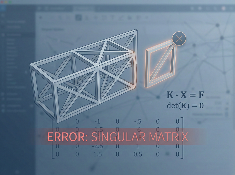
A singular matrix is one whose determinant equals zero, which means it can’t be inverted. And if the stiffness matrix can’t be inverted, the software can’t solve for displacements.
Here’s why this matters: the fundamental equation of structural analysis is:
$$\mathbf{K} \cdot \mathbf{X} = \mathbf{F}$$where K is the stiffness matrix, X is the displacement vector, and F is the force vector. To find displacements, the software needs to compute:
$$\mathbf{X} = \mathbf{K}^{-1} \cdot \mathbf{F}$$If K is singular (determinant = 0), that inverse doesn’t exist. The math breaks down.
“Singular matrix” isn’t a software bug—it’s the math telling you your structure is physically unstable. The model can move without any resistance.
Why Every Unconstrained Member Is Singular
Every member stiffness matrix is singular before you apply supports.
Think about a single beam floating in space with no connections to anything. It has six degrees of freedom. You can:
- Translate it horizontally
- Translate it vertically
- Rotate it
These are called rigid body motions. The member doesn’t deform—it just moves as a rigid object. No internal stresses develop, and no forces are required to make it happen.
Mathematically, when you assemble the 6×6 member stiffness matrix for a standard beam-column element, you get something like:
$$\mathbf{k} = \begin{bmatrix} \frac{AE}{L} & 0 & 0 & -\frac{AE}{L} & 0 & 0 \\ 0 & \frac{12EI}{L^3} & \frac{6EI}{L^2} & 0 & -\frac{12EI}{L^3} & \frac{6EI}{L^2} \\ 0 & \frac{6EI}{L^2} & \frac{4EI}{L} & 0 & -\frac{6EI}{L^2} & \frac{2EI}{L} \\ -\frac{AE}{L} & 0 & 0 & \frac{AE}{L} & 0 & 0 \\ 0 & -\frac{12EI}{L^3} & -\frac{6EI}{L^2} & 0 & \frac{12EI}{L^3} & -\frac{6EI}{L^2} \\ 0 & \frac{6EI}{L^2} & \frac{2EI}{L} & 0 & -\frac{6EI}{L^2} & \frac{4EI}{L} \end{bmatrix}$$This matrix is always symmetric (thanks to Betti’s reciprocal theorem), and it’s always singular. If you calculate the determinant—it’s zero. Every time.
That’s not a flaw. That’s physics. An unconstrained structure should have a singular stiffness matrix because it can undergo rigid body motion. As we explore in Frame Stiffness vs FEA, understanding how these stiffness matrices work is fundamental to knowing when your analysis results are trustworthy.
How Boundary Conditions Save the Day
So if every member matrix is singular, how does analysis ever work?
The answer: boundary conditions eliminate rigid body motions.
When you pin a support, you’re telling the software “this displacement is known—it’s zero.” When you fix a node, you’re prescribing zero translation and zero rotation. These constraints remove degrees of freedom from the unknown column and put them into the known column.
Supports don’t just hold your structure up—they mathematically transform a singular system into a solvable one by removing rigid body modes.
Common Causes of Singular Matrix Errors
Now for the practical part. When you see this error, what should you check?
1. Missing Supports
The most obvious cause: your structure is literally floating. In 2D, you need at least three DOFs restrained to prevent rigid body motion (two translations plus rotation). In 3D, you need at least six.
But it’s not just about quantity—it’s about arrangement. Three pinned supports along a single line? Still unstable in rotation about that line.
2. Unconnected Nodes
Did you draw members that look connected but actually have separate nodes at the same location? Most software has a “merge nodes” function or tolerance setting. If nodes aren’t merged, the structure is effectively discontinuous.
3. Mechanism Within the Structure
Internal hinges without proper support can create mechanisms. A simply supported beam with a hinge at midspan has no rotational restraint at the hinge—it’s a mechanism unless you add additional supports.
4. Released Connections Gone Wrong
End releases (moment releases, shear releases) are powerful but dangerous. Release too many degrees of freedom at a joint, and you’ve created a local instability. A classic example: two beams meeting at a joint, both with moment releases at that joint, and no rotational restraint from a column. The joint can spin freely.
5. Members with Zero Stiffness
Did you accidentally assign zero area or zero moment of inertia? Did you use a material with zero modulus? The software might not catch this until it tries to invert the matrix.
6. Isolated Substructures
Sometimes models have pieces that aren’t connected to the rest. A stray node, a member floating off in space, a duplicate grid that didn’t get deleted. The isolated portion is unconstrained even if the main structure is properly supported.
Debugging Strategies
When you hit a singular matrix error, here’s a systematic approach:
1. Check the error message details
Many programs tell you which DOF is problematic. ETABS might say “Instability at joint 47, DOF U2.” That’s your starting point.
2. Isolate the problem
If you have a large model, try analyzing a portion. Remove everything except the area around the suspected instability. Does it still fail?
3. Add temporary supports
If you’re not sure where the mechanism is, add redundant supports throughout the model. If it runs, remove them one by one until you find what’s needed.
4. Check connectivity
Use the software’s “select connected” function. Starting from a support, can you select the entire structure? If not, something’s disconnected.
5. Review releases
Create a display filter showing all end releases. Look for joints with too many releases converging.
6. Visualize displaced shape at zero load
Some programs let you animate the instability modes. This can reveal exactly how your structure wants to move.
For EITs: Singular matrix errors are a rite of passage. Don’t panic—they’re fixable. The error is telling you something real about your model’s stability, and finding the cause teaches you a lot about structural behavior.
For Others: When reviewing junior engineers’ models, checking for proper boundary conditions should be near the top of your list. It’s one of the most common sources of errors.
Putting It Into Practice
Here are two things you can do right now:
Review your current project for unnecessary complexity in support conditions. Are there releases that could create unintended mechanisms?
Test your understanding by creating a simple model with an intentional instability (missing support, excessive releases) and see what error message you get. Then fix it.
And here’s a question for your next team discussion: If a 3D structure requires six restrained DOFs minimum, why do we often get away with modeling pin-pin beams (only two restrained DOFs per end) without instability errors? What’s implicitly happening in those models?